We may receive a commission when you use our affiliate links. However, this does not impact our recommendations.
The Trapped Reverse Chuck, how to build and use this must-have bowl-turning jig.
In bowl turning, good craftsmanship requires that the bottom show no evidence of how the bowl was mounted. It’s also important to learn how to keep the chuck from dictating key aspects of the design, such as the bottom’s shape, diameter, and height.
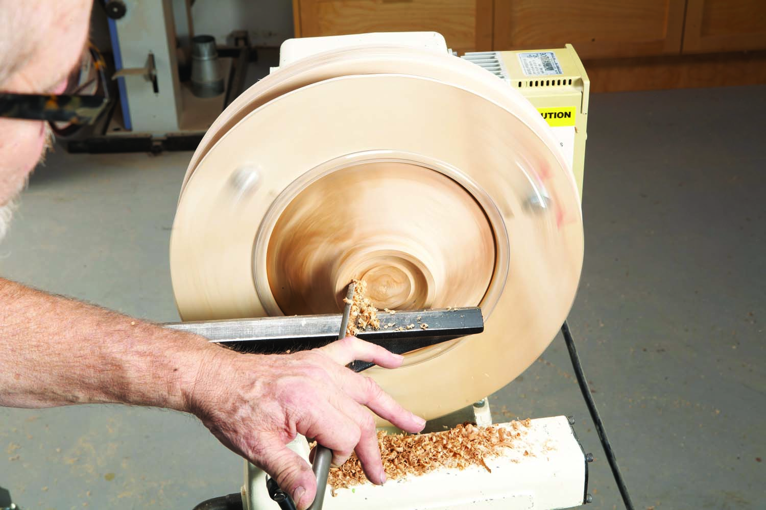
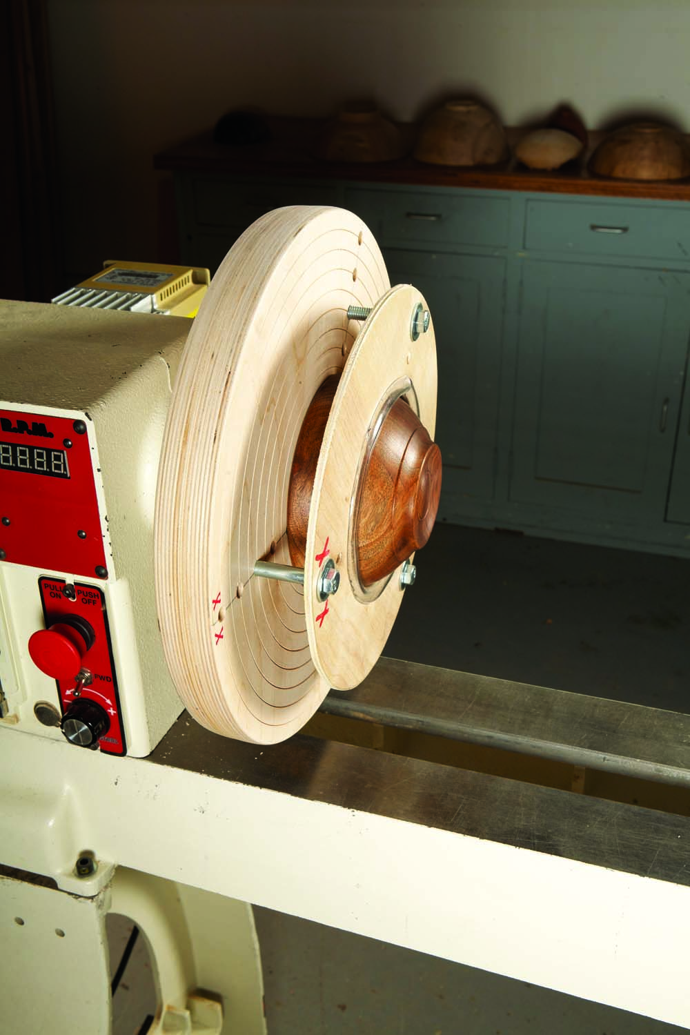
Photo A. Use this chuck to remove screw holes and chuck marks, create a hollowed base with a rim, add details such as lines or beads, or turn a fully rounded bottom.
This shop-made trapping chuck will dramatically improve the quality of your work in both of these important areas (Photo A). It allows full access to the bottom of a bowl or vessel and frees you from limitations caused by a faceplate or any other chuck. This chuck securely holds the work, so it can’t go flying across the shop—a benefit that’s absent from most other such chucks, both shop-made and commercial.
Make the chuck’s base
This chuck has two basic parts, a base on which the work is mounted and a ring to clamp the work to the base. Typically, rings of different diameters are used to clamp work of different sizes. Start by gluing together two thicknesses of 3/4″ Baltic birch plywood to make the chuck’s base. Use yellow wood glue. Size the plywood to make a disc that that’s slightly less than the maximum diameter your lathe allows. Let the glue cure for a day. Then bandsaw the disc.
Choose a faceplate to dedicate to the chuck. I suggest at least 3″ dia. for chucks up to 12″, 4″ dia. for chucks 14″ to 16″, 6″ dia. for 18″ to 24″ and bigger still for lathes with larger capacities. Larger faceplates increase the stability of this chuck, so always err on the larger side.
Center the faceplate on the disc and mount it. Then turn the disc to a cylinder, using a bowl gouge. Plywood turns poorly and dulls tools quickly, so work slowly, make light cuts and keep your gouge sharp. Finish by power sanding, using a sanding disc mounted in a drill to make sure the rim has no sharp corners or splinters.
In order to hold the work, the disc must have a flat surface that’s perpendicular to the axis of the lathe. Use a square-end scraper to true the disc (Photo 1). Then lightly sand the surface.
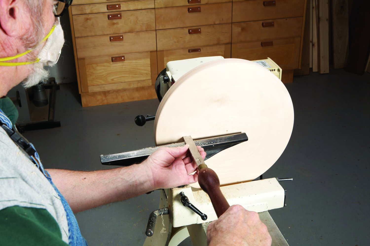
Photo 1. Flatten the face of a disc turned as large as your lathe will allow by lightly facing across the plywood. This disc will become the chuck’s base.
With the lathe running at slow speed (less than 400 rpm), use a pair of solid dividers (see Sources) held flat on the tool rest to mark lines every 1/2″, starting about 1/2″ from the rim and stopping about 4″ from the center. Then deepen these lines with the long point of a skew chisel (Photo 2).
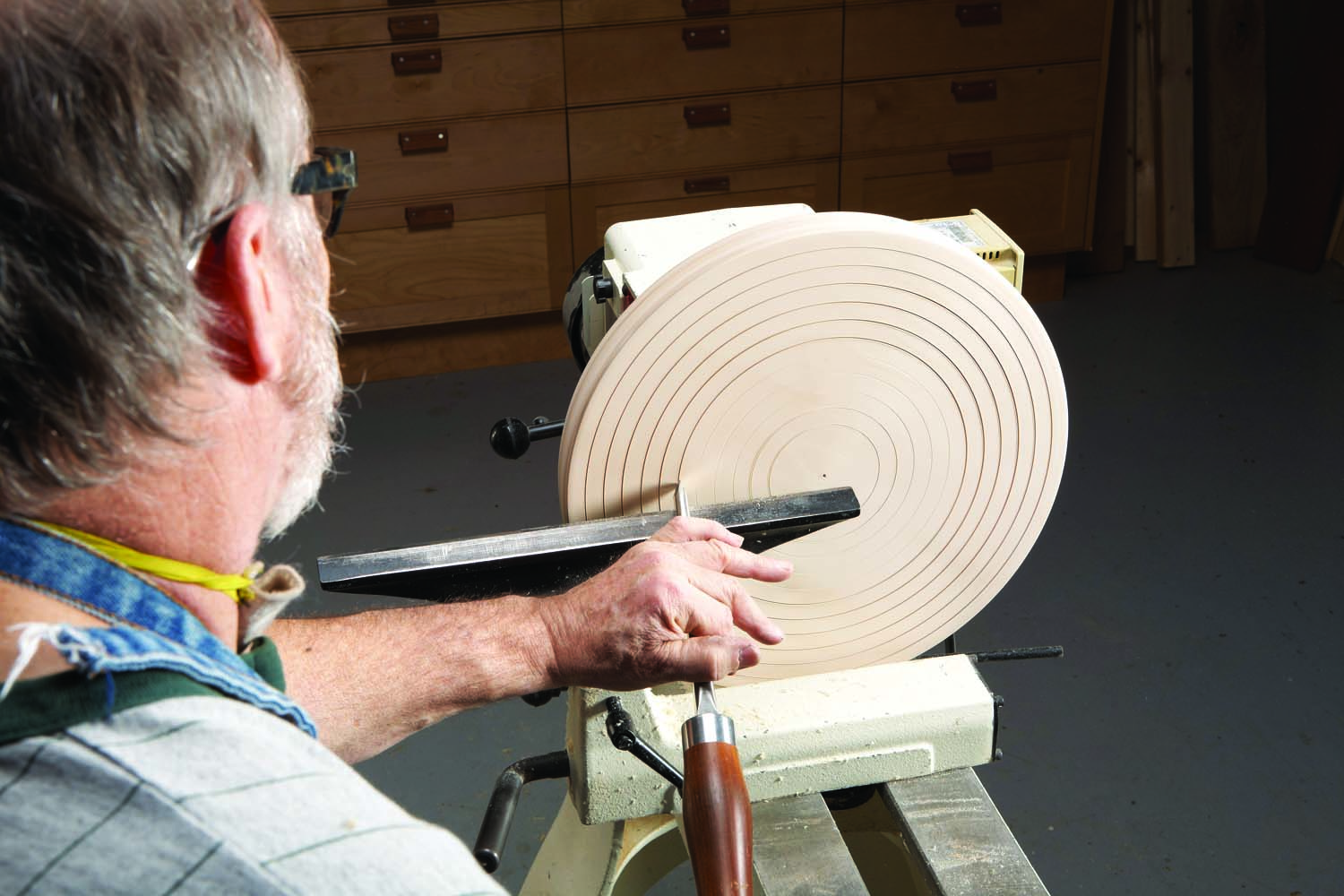
Photo 2. Cut shallow grooves every 1/2″ with the skew chisel to deepen scored lines made with dividers. Orient the skew with its long point down.
Remove the faceplate and place the disc on a flat surface. Then draw lines that divide the disc’s face into three pie-shaped sections that are (roughly) equal in size. Permanently mark one of these lines—this mark will be used to index the other parts when building and using the jig. Drill 5/16″ dia. mounting holes along the three lines for the bolts that will hold the ring (Photo 3). Start at the outer ring you cut earlier and space the holes 1″ apart down to the 4″ mark. Use a new or very sharp bit, make sure it’s perpendicular to the drill press table and install a flat, sacrificial board underneath (plywood works well) to eliminate tear-out.
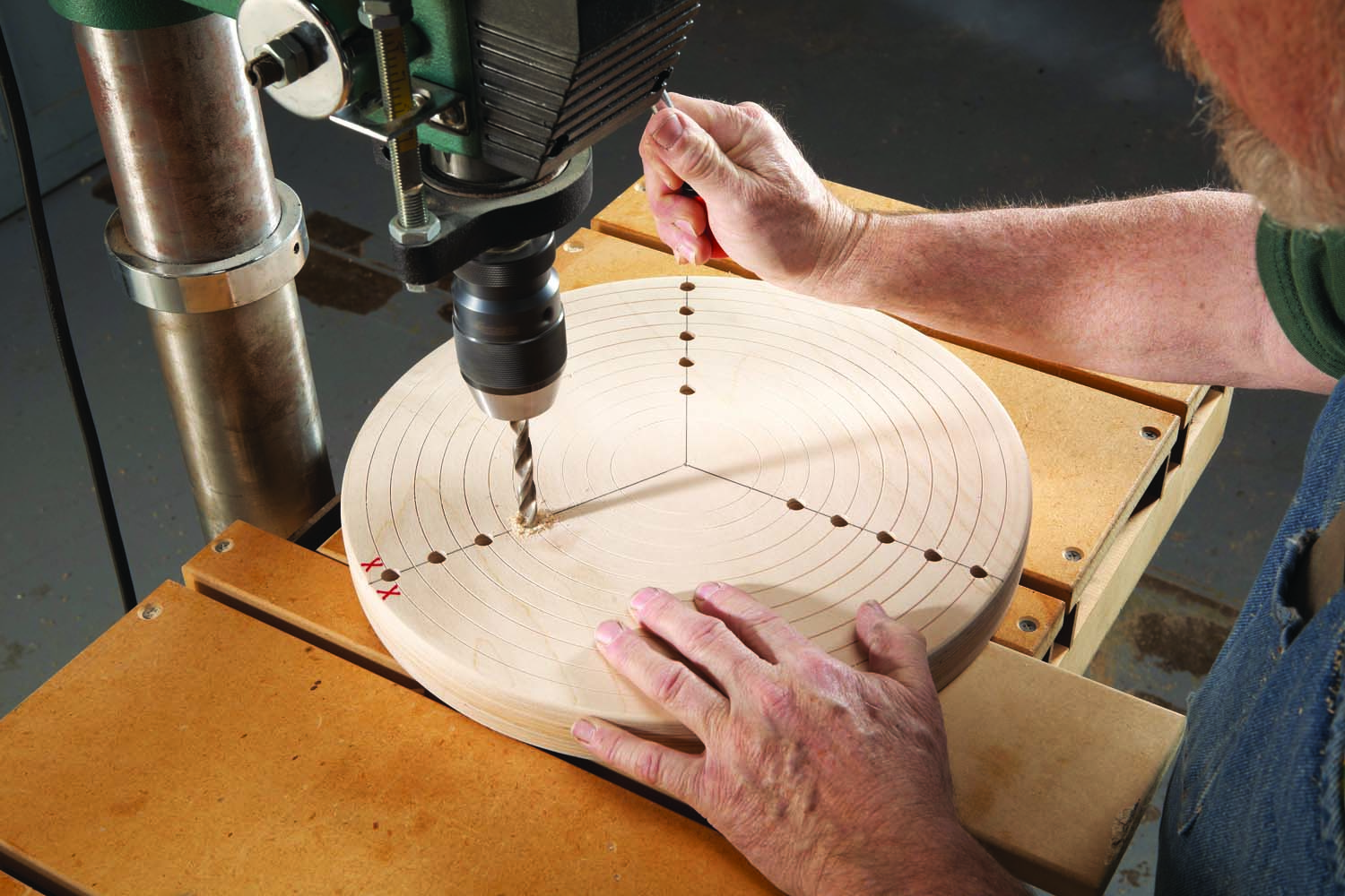
Photo 3 Drill holes through the disc on lines drawn to divide it into three equal segments. Complete the base by marking one of the lines for indexing.
Make the rings
Attach a hardboard disc to the base to create a template for making the rings (Photo 4). Index the hardboard to indicate its “key” line of holes and its outward face (when mounted on the base). Then flip over the assembly and use the holes in the base to drill through the hardboard (Photo 5).
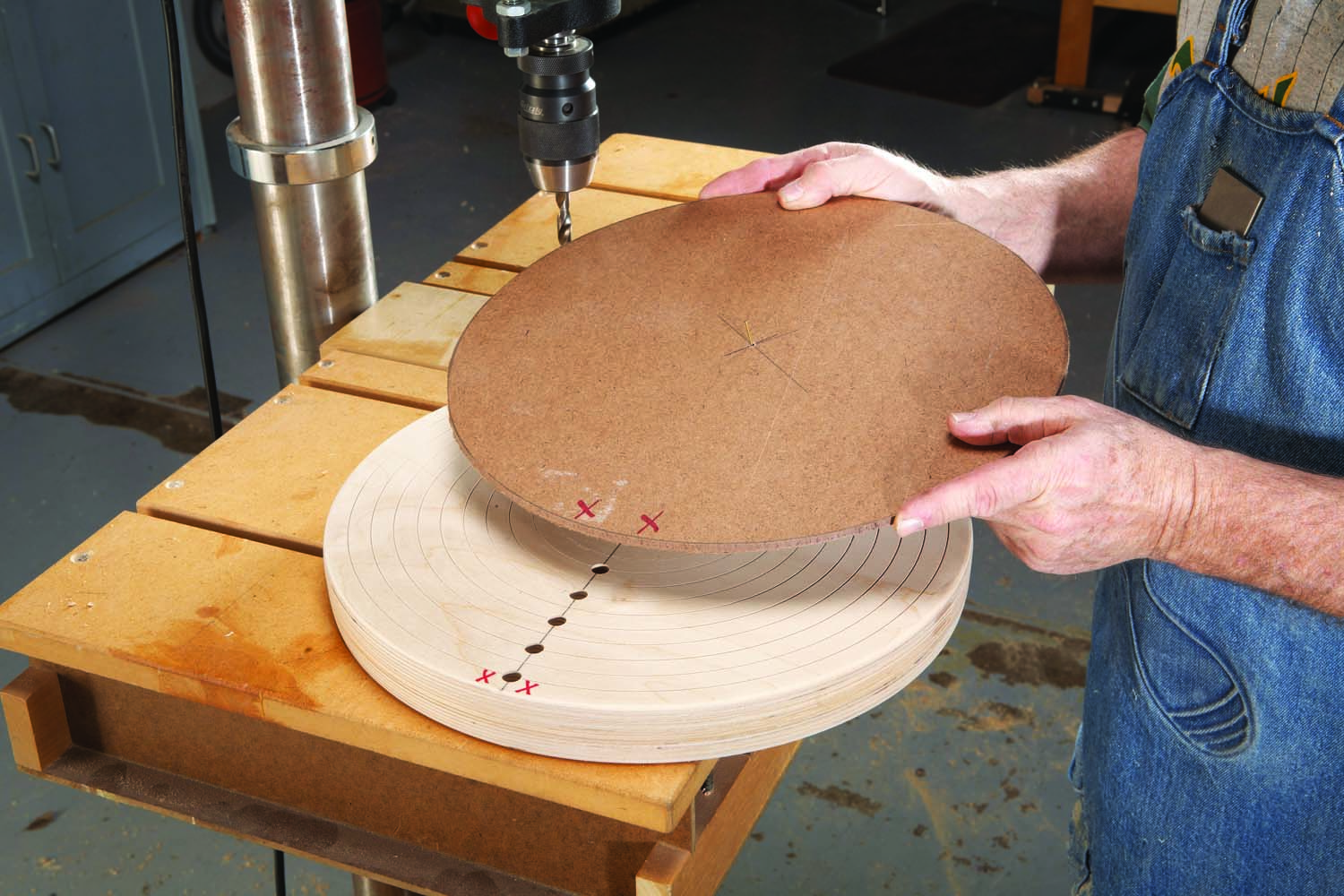
Photo 4. Mount a hardboard disc of the same diameter on top of the base, using a tack in the center and double-sided tape near the edges. Index the disc.
Plan to cut 10 rings at first: four the same diameter as the base, four two-thirds the diameter, and two half the diameter. Once you start using the chuck, you’ll make many more. The size of the center hole and where the drilled holes are located on the ring are the two variables, and they depend upon the piece you intend to hold. Cut the rings from 1/4″ or 3/8″ thick Baltic birch plywood. The 1/4″ stock is fine for smaller chucks, but I tend to go to 3/8″ or even 1/2″ for larger rings and larger diameters.
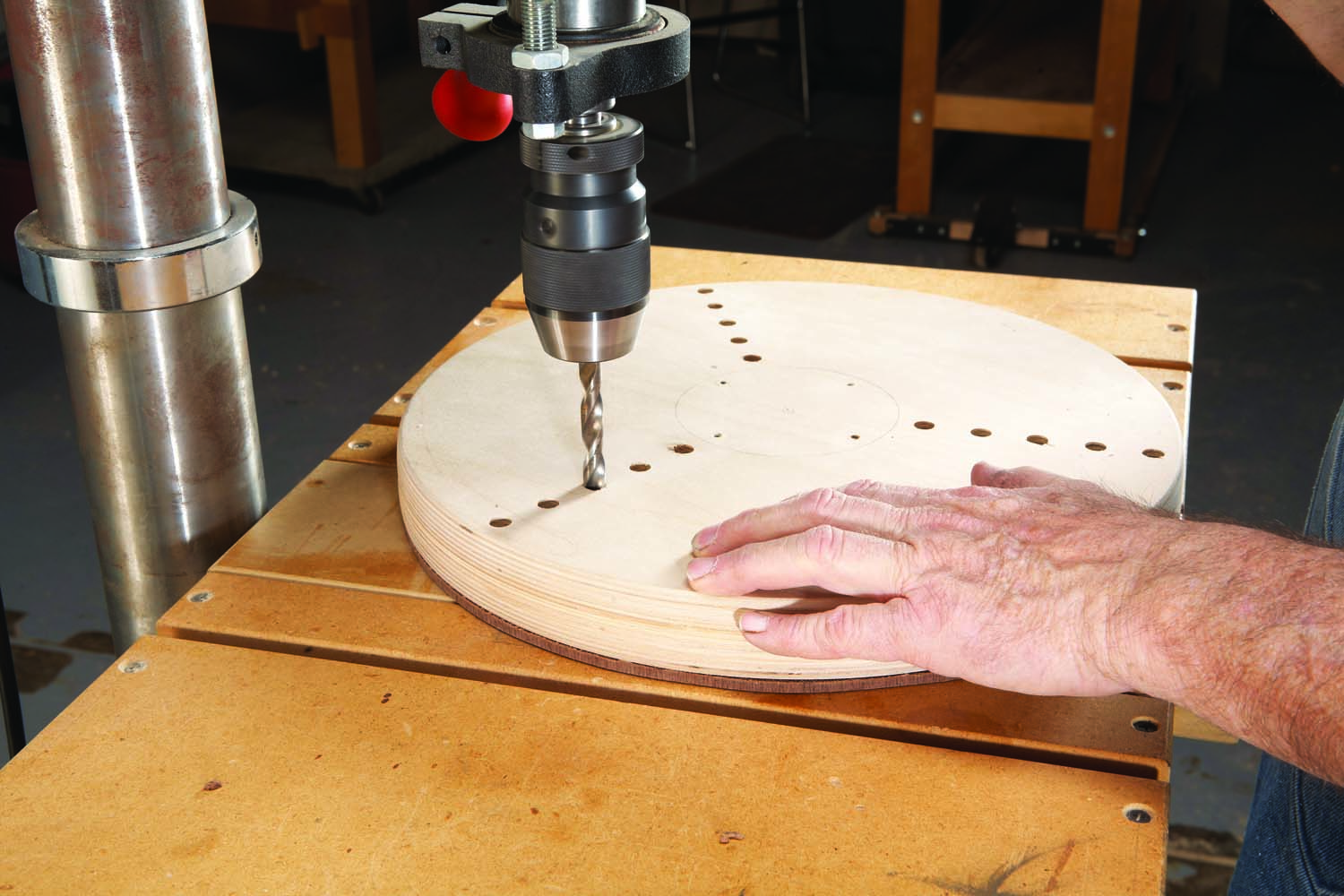
Photo 5. Drill through the hardboard disc at every hole in the plywood base to create a template for drilling the chuck’s rings.
Cut the plywood into discs the same diameter as the template. Then use the template to mark the bolt holes for drilling (Photo 6). For slightly more adjustability, I sometimes use a bit that’s 1/64″ larger than the bolts to drill these holes. Drilling as for the template (that is, using the base to guide the bit) is another option. As before, transfer the index marks to the plywood disc and mark its outside face.
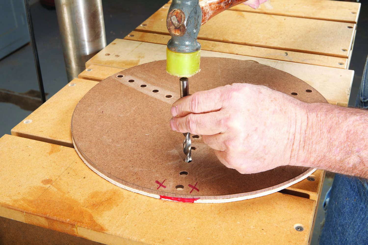
Photo 6. Use the template and a brad point bit to locate the holes on a plywood disc of the same diameter. Remove the template. Then drill the holes.
Re-install the faceplate on the chuck’s base, making certain the base mounts flush. Lay the hardboard and one of the rings on top of the base, with all the index marks properly oriented. Then lash all three pieces together using 5/16″ x 2-1/2″ long coarse-thread bolts, washers and wing nuts.
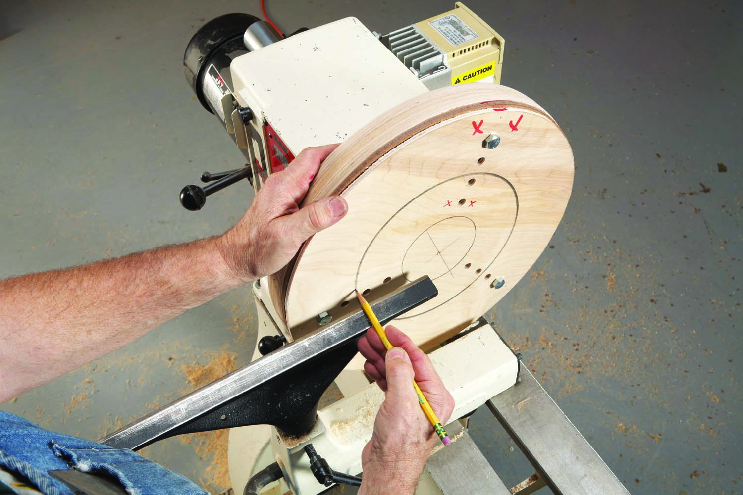
Photo 7. Mark the plywood disc for cutting into rings after mounting the base on the lathe and bolting on the template and disc.
Mark each disc for cutting into rings (Photo 7). Vary the center opening’s size in each ring. Some discs will yield two rings. For the 14″ chuck shown here, I made openings from 3″ to 12″ in one-inch increments. Rings between these sizes can be made as necessary.
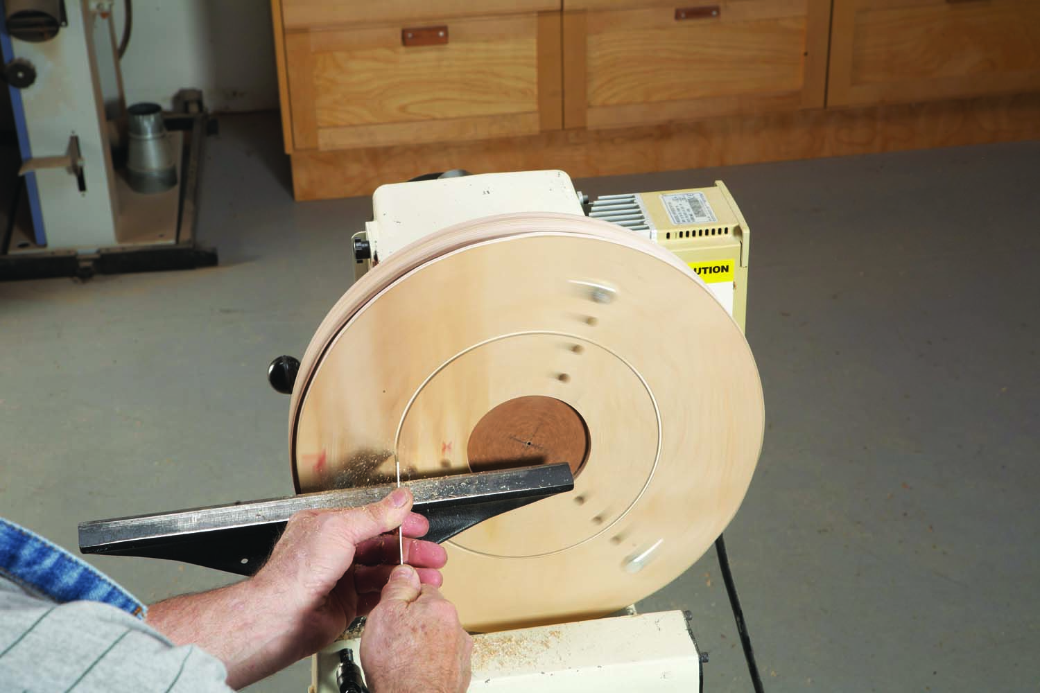
Photo 8. Cut through the plywood disc to create the two rings. Cut out the waste at the center first. Then cut out the small ring to create the larger ring.
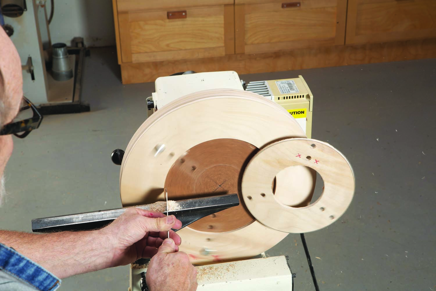
Photo 8.5
Cut through the plywood disc to create each ring, using a thin-kerf parting tool (Photo 8). Run the lathe at 500rpm or slower during this process. Engage the tailstock (when possible) to hold the cut-through disc in place and wear a full-face shield.
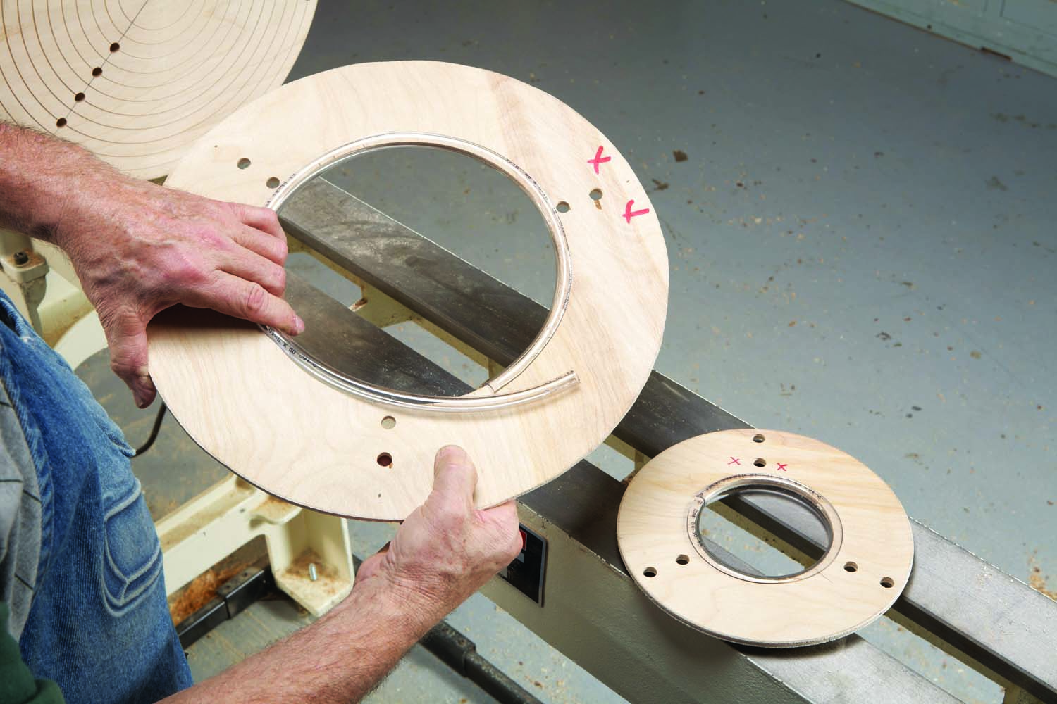
Photo 9. Line each plywood ring with clear rubber hose that’s been split with a utility knife.
After all the rings are cut, lightly sand all their edges and clearly mark the index points. Then line the center opening in each ring with 3/8″ I.D. clear rubber hose (Photo 9). You’ll need about 12′ of this clear hose to line the ten rings (see Sources). Cut the hose about 1/8″ shorter than the circumference of each hole. Notice how the hose curls—then cut on the back of the curl, using a sharp knife. Lay the hose down and cut with the blade going away from you! Press on the hose—its natural curl will hold it in place.
Use the chuck
Set the piece you’re working on rim-down on the chuck and center it using the circular cut marks (Photo 10). Then decide which ring to use by placing each likely candidate on the bowl with the index marks and holes in alignment (Photo 11). Does the center opening sufficiently grip the bowl while allowing full access to both its lower outside portion and its underside? Are the drilled holes positioned to allow the bolts to pass through without contacting the bowl?
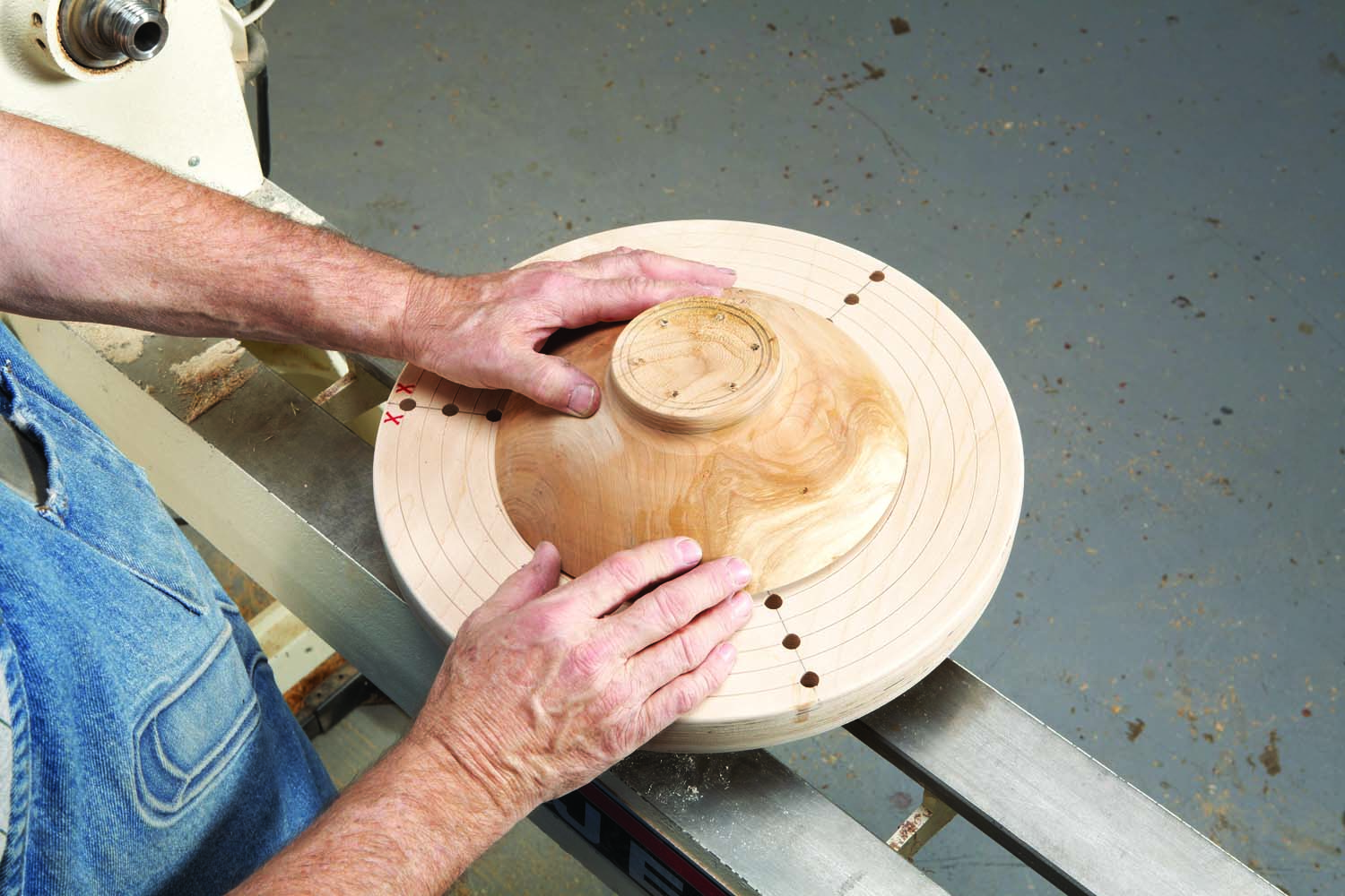
Photo 10. To use the chuck, start by roughly centering a bowl on the appropriate groove cut in the base.
Select the right bolt. As nearly every bowl is different, you’ll need bolts of many different lengths to use with this chuck. I recommend buying sets of three 5/16″ coarse-thread bolts, washers and wing nuts in one-half inch increments from 2″ to 8″. If having bolt heads whizzing past so near you and the work is unnerving, substitute carriage bolts.
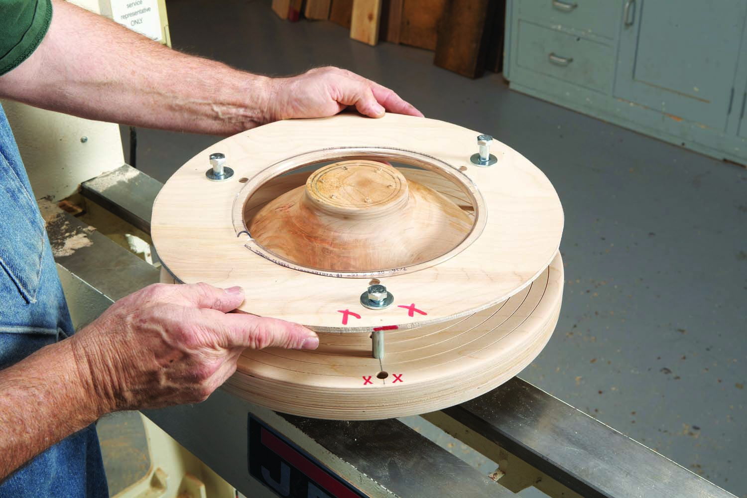
Photo 11. Install the ring and use it to clamp the bowl to the plywood base using bolts, washers and wing nuts.
With one washer on the ring under the bolt’s head, make sure its threaded portion sufficiently protrudes through the base to install a washer and wing nut. If the bolt is slightly too long, so its unthreaded shaft appears, it’s okay to use additional washers under the wing nut. Lightly tighten the wing nuts to secure the piece.
Screw the chuck and mounted work onto the lathe. Then precisely center the work. It’s helpful to have already marked the center on the bottom. One method is to use a simple center finder (see Sources). Then you can simply bring up the tailstock and move the work within the chuck to align the hole in its bottom with the tailstock’s center.
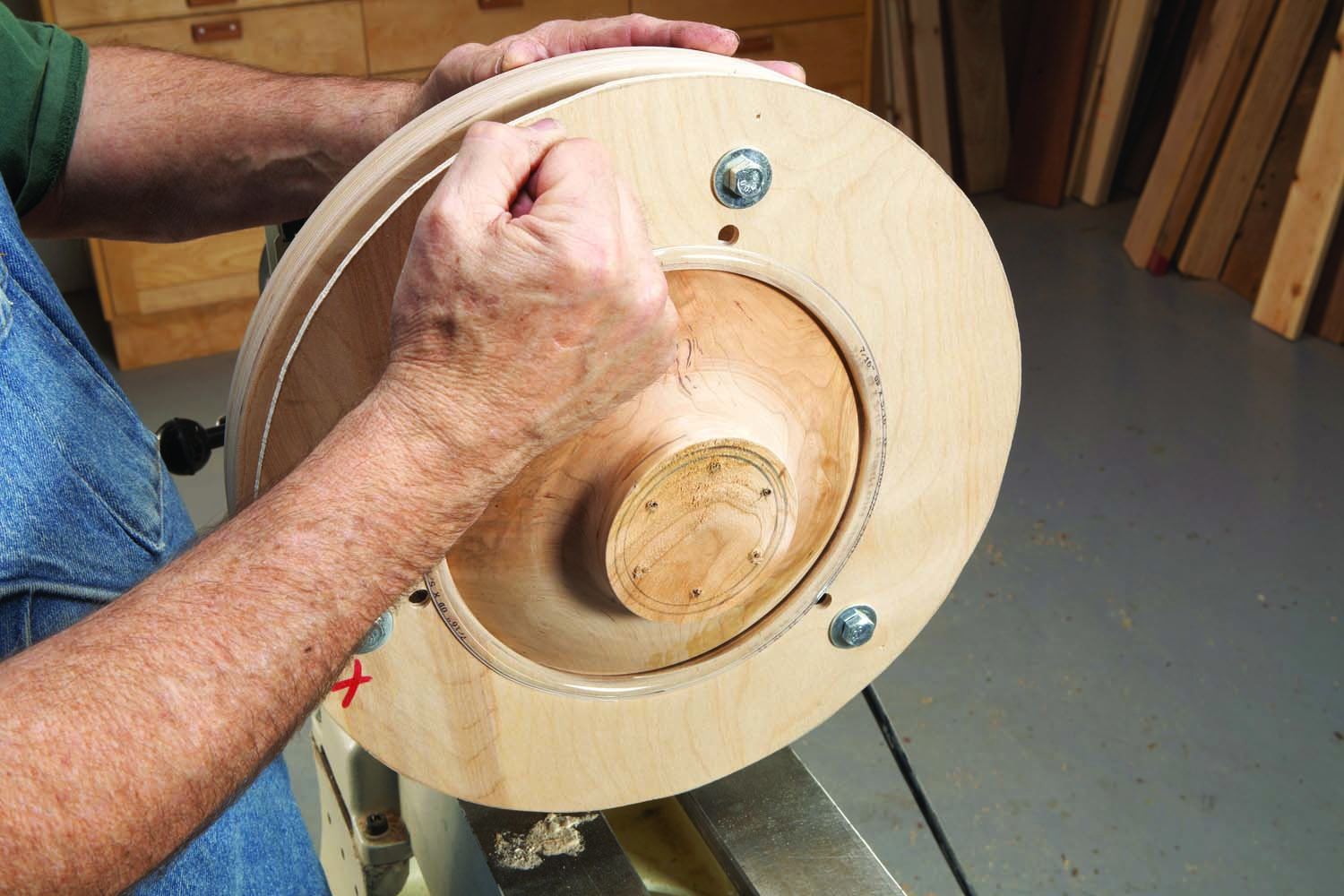
Photo 12. Center the bowl after mounting the chuck on the lathe. Mark the high spot and then gently tap this spot as necessary. Then tighten the wing nuts.
Fortunately, it’s fairly easy to center the work even if it doesn’t have a center mark (Photo 12). Rotate the chuck by hand. Place a pencil on the tool rest and slowly move it forward to mark the high spot on the rotating work. Then nudge the work slightly away from that high spot by pushing or tapping at the center of the line. Rotate the chuck and test again with the pencil. When the work is centered (or very nearly centered) the line will travel fully (or mostly) around the piece. When the bowl is centered (or very nearly), tighten the wing nuts and bring up the tailstock center.
Finish turning the lower outside portion of the work and finalize its base diameter. If you cut in at the base to remove mounting holes on the bottom, you’ll also be changing the work’s height. There’s no need to run the lathe very fast during these operations, as you have a lot of mass on the machine. Finish-sand the newly-turned portion of the work as necessary.
Pull back the tailstock and plan the look of the work’s bottom. I like a turned piece to sit on a foot, with a concave region from the foot to the center. With this chuck you can deep-hollow a foot, add details such as beads or lines or any other surprise you may wish to give the viewer. Finish-sand the bottom to complete the work. Remove the chuck with the work still attached and place it the bench. Then remove the wing nuts, bolts and ring.
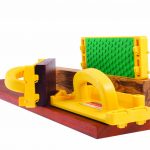
Sidebar: Mount Unusual Shapes
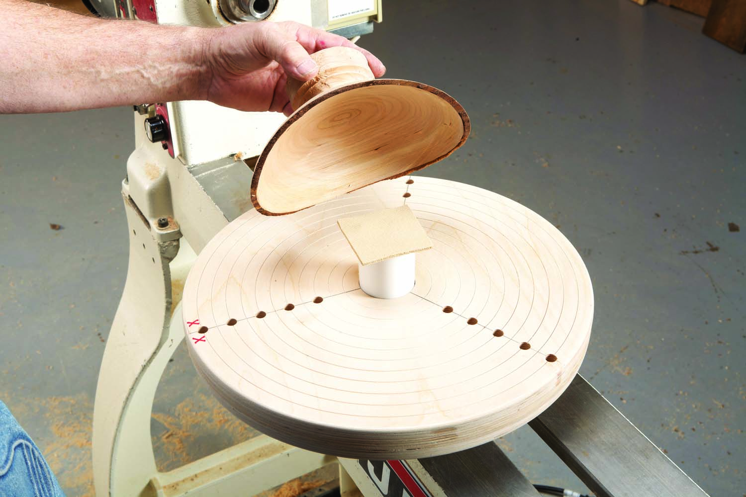
Photo B
This chuck can be used to mount work with natural edges, thin walls or delicate rims (Photo B). Cut a groove in the face of the chuck’s base to tightly house a short piece of thick-wall (schedule 40) PVC pipe—usually just long enough to raise the work’s rim off the face. Use a scraper to lightly face off the protruding end of the pipe. Then glue on a 1/8″ thick piece of textured rubber (such as a router mat) with CA glue. Position the work on the padded pipe, install a ring and you’re ready to go.
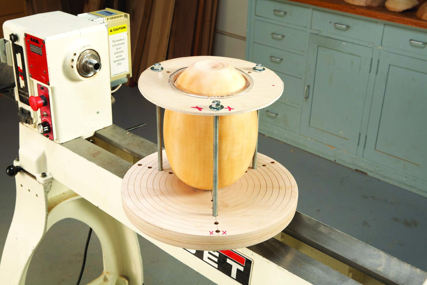
Photo C
You can also mount tall work by using threaded rod with washers and nuts on both ends (Photo C). Most other reverse chucking systems don’t have this capability.
Special Thanks
Eldon Rebhorn showed a version of this chuck in a book written in the 1960s. A few years later Hawaiian turner Jack Straka developed and refined this idea.
Bio
Alan Lacer is a turner, writer, demonstrator and instructor living near River Falls, WI. For more information, visit alanlacer.com.
Here are some supplies and tools we find essential in our everyday work around the shop. We may receive a commission from sales referred by our links; however, we have carefully selected these products for their usefulness and quality.