


We may receive a commission when you use our affiliate links. However, this does not impact our recommendations.
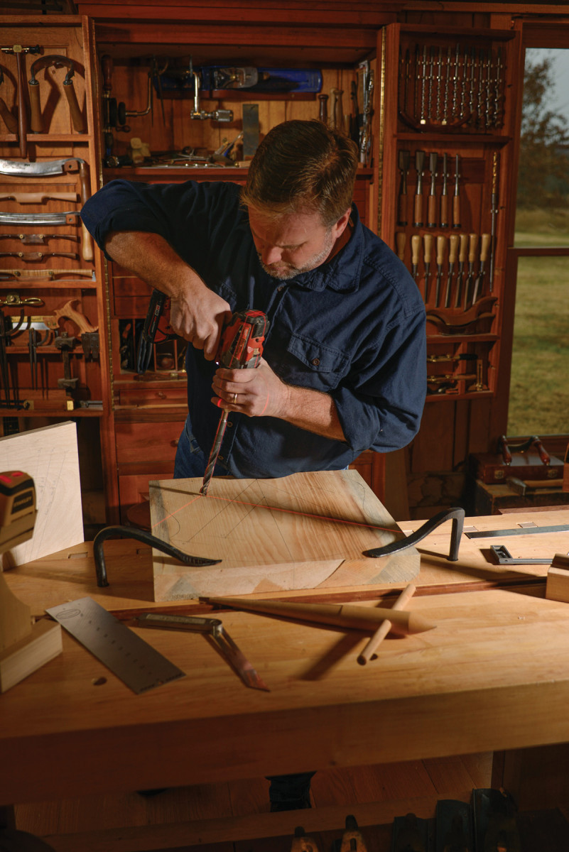
Affordable line lasers and a simple setup make for perfect angled drilling.
I’m a 21st-century Windsor chairmaker. I build chairs using mostly hand tools: froes, drawknives, spokeshaves, travishers, scorps, an adze and other tools that, even in the fast-paced computer age, still comprise the most efficient way to follow the inherent strength of fibers in a tree.
I also drill lots and lots of holes. An average Windsor can have up to 40 holes, and most of these holes are drilled at compound angles, which in part give a Windsor strength, stability and grace. Compound angles can be achieved many ways, such as tilting the table on a drill press, and employing various jigs or bevel gauges and mirrors using sightlines. It’s this last method – sightlines – that I have been using for years to drill my chairs, which in turn sparked a method of drilling compound angles with lasers. Yes “lasers.” Not the kind that get you in trouble on airplanes, but very inexpensive line lasers.
Several years ago, I was teaching a student to build a Windsor stool. And as we were setting up the bevel gauges and mirrors to drill the stool’s top, he mentioned how hard it was to look at both mirrors and focus on the bevels in two directions. We talked about how nice it would be to look at one spot while drilling these holes, and that’s when line lasers popped into my head. Off to the hardware store we went and, sure enough, they had what we needed.
Teaching has been the biggest gift to my career – it keeps me focused on practicing and fine-tuning my methods while bouncing ideas off students who are usually smarter than I am. They always have great input. So in early February 2011, my technique for drilling compound angled holes with lasers was born.
For someone not used to looking at sightlines and bevel gauges, consistently drilling or reaming at the proper geometry is a huge challenge. We used to get close – and for chairs most of the time close is acceptable – but now with the help of lasers my students simply look at two intersecting laser lines on the drill or reamer with a confidence that I’ve never before seen. And a laser guide setup is inexpensive and simple to set up – believe me, if it were not simple I wouldn’t fool with it.
Sightlines
Sightlines. Sightlines are based on the rake and splay of a chair leg or arm post.
Chairmakers use sightlines to determine compound-angled holes. A sightline is a line that passes through a leg when it appears 90° (vertical) to our eyes. Yes, a right angle in chairmaking! The resultant angle is how much the leg leans forward or back along the sightline. These are based on rake (front to back) and splay (side to side) angles – concepts explained in detail in Peter Galbert’s “Chairmaker’s Notebook” (Lost Art Press) and Christopher Schwarz’s “Compound Angles, No Math” (June 2015 Popular Woodworking Magazine, issue #218).
Build Some Laser Bases
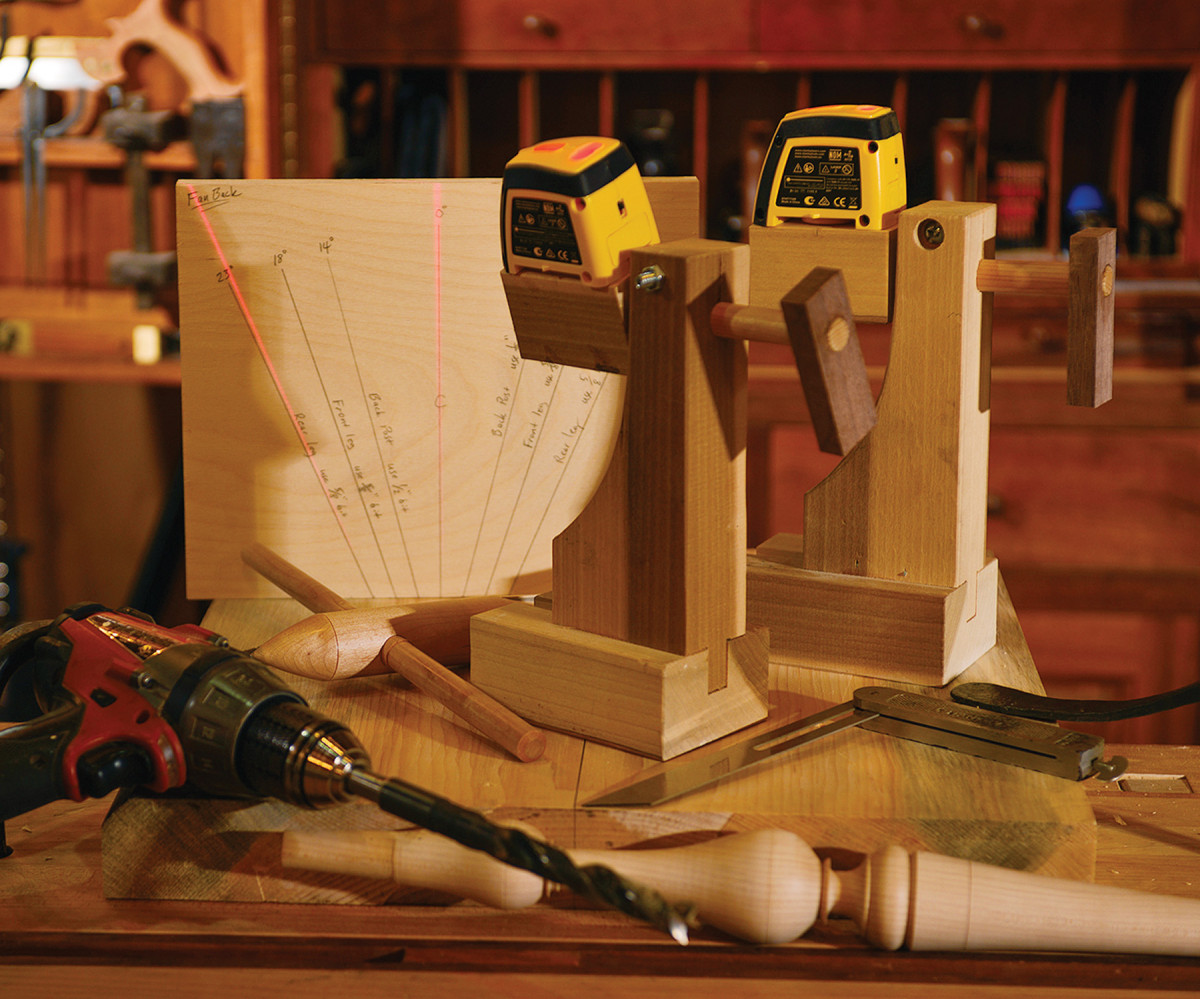
Scrap bases. Rotating bases position the lasers 9″ off the top of the workbench, where the laser guides work best.
First, head to your local hardware store and purchase two cheap line lasers. Your new lasers will have a small magnet on the bottom that will hold them to the bases, and out of the package I had to lap the plastic casing on the bottom of each laser on sandpaper to keep them from rocking. (Did I mention they were cheap?)
I built the rotating bases from scrap hardwood salvaged from the kindling bin. The laser works best sitting 9″ off the workbench. Build the base thick for stability. I use a 5⁄8” dowel that slips through a slotted hole in the neck with a pinch bolt, and the laser sits magnetized on a metal nut embedded and glued into the pivoting head. I also glued some rubber to the bottom of the base to keep the unit from sliding on the workbench. Once you’ve built your bases, you are ready for some sightlines.
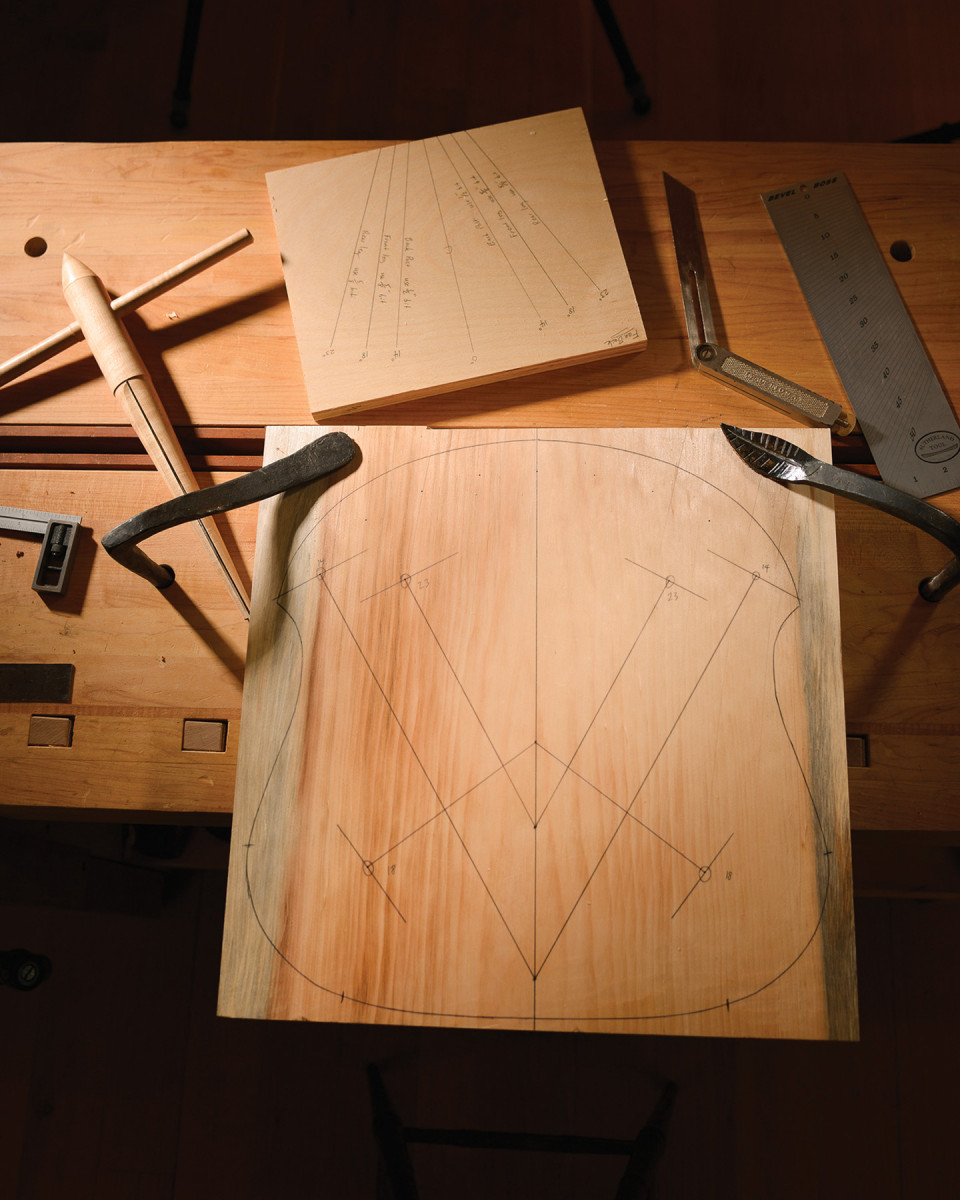
Make an Angle Gauge
Using a simple 10″ x 12″ bit of plywood cut nice and square, draw a vertical 90° centerline. Now map out your resultant angles in both directions, on either side from center, with a bevel gauge and label each angle you want to drill above each corresponding line. This is what we will be using to set the lasers before drilling. I like to make a dedicated angle gauge for each type of chair I make.
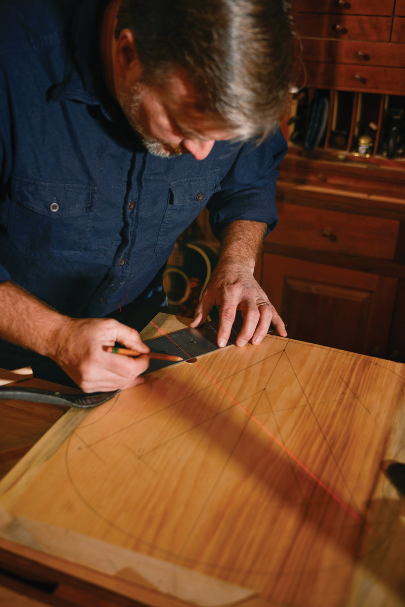
Layout
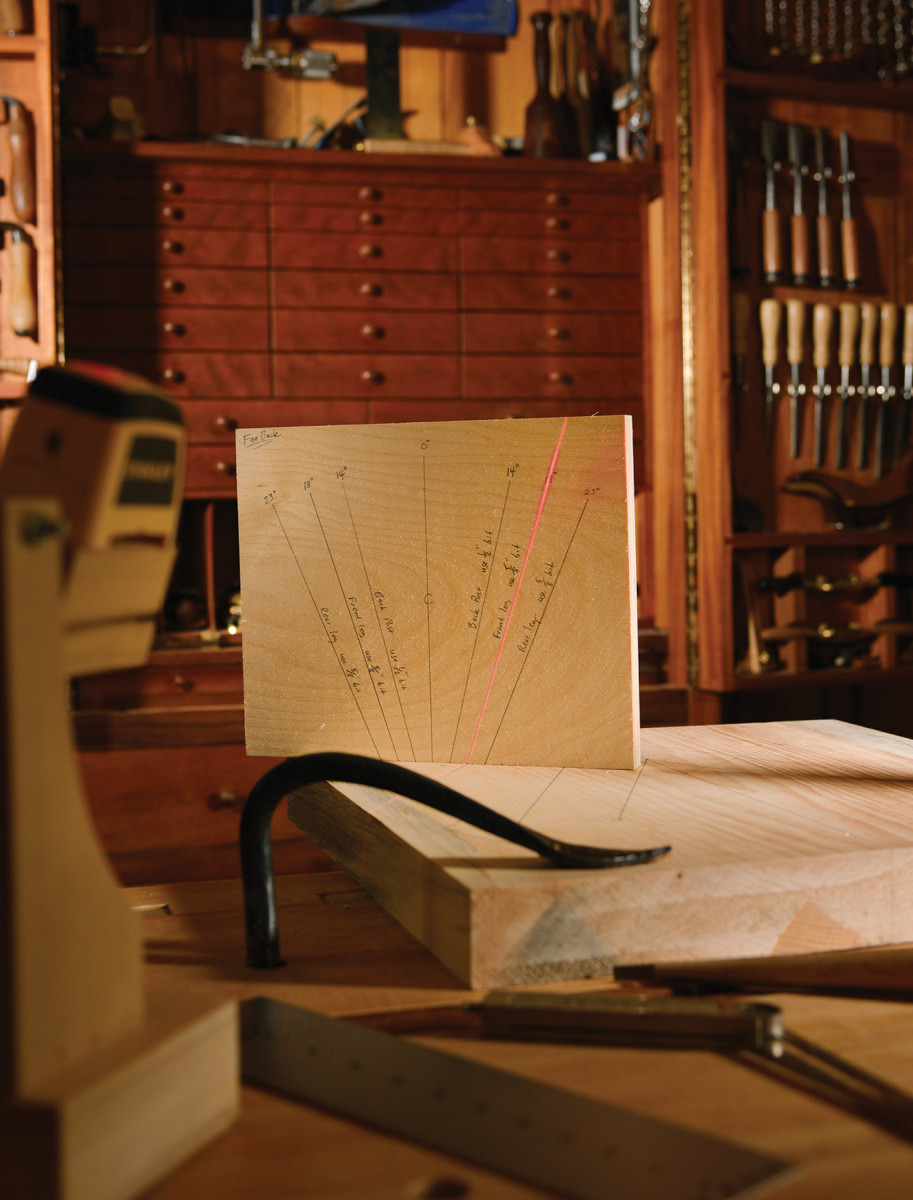
Angle gauge. Make a plywood angle gauge marked with each angle a project calls for.
Now it’s time to lay out your seat pattern (or whatever you are drilling) with the leg hole locations and sightlines. At the location of each hole to be drilled, draw a short perpendicular line. Set the first laser down the sightline toward the hole at 90° to the seat. Place the second laser down the perpendicular line set to the resultant angle. (Just be sure you are leaning in the correct direction.) That’s it – simple! This creates the crosshatch – two laser lines – to follow down the hole.
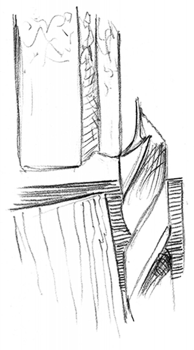
Grinding Drill Bits
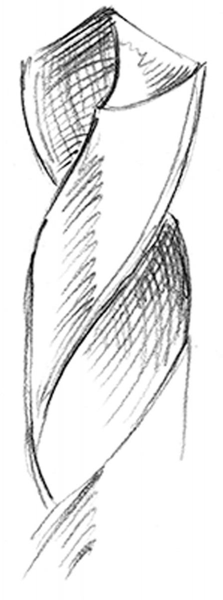
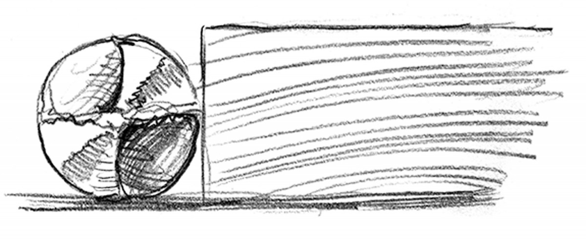
1. Start with a machinist’s bit.
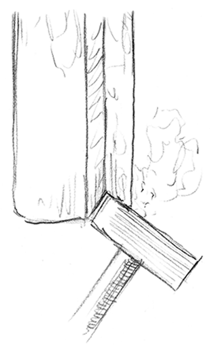
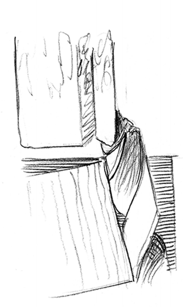
2. Dress a notch in the side of the grinding wheel. The flat of the wheel is still accessible for other grinding tasks.
3. Clamp a block at 4° to the axis of the wheel to form the angle of the center spur.
This is the process for transforming standard machinist’s twist bits into wood-cutting brad-points. I start with high-quality high-speed steel twist bits I purchase from a machinist supplier, Victor Machinery, in New York.
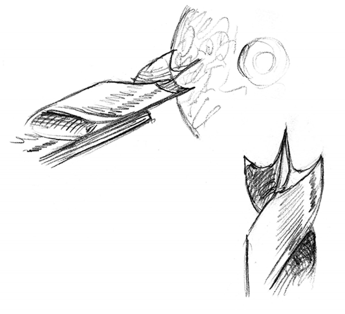
The angle of the tool rest determines the rate of feed that the bit will cut. Block control. The block on the tool rest controls the angle that the bit is presented to the wheel.
Then I use my wheel dresser to make a shape on the edge of my grinding wheel that will correspond to the wing of the brad-point. Using a coarse wheel for the initial grinding will speed the removal of the material, but any wheel can be used as long as it is well-dressed and used with light pressure. I always make sure that the corner is lower than the flat of the wheel that I use for general grinding. The sharper the corner, the deeper the wings on the resulting bit.
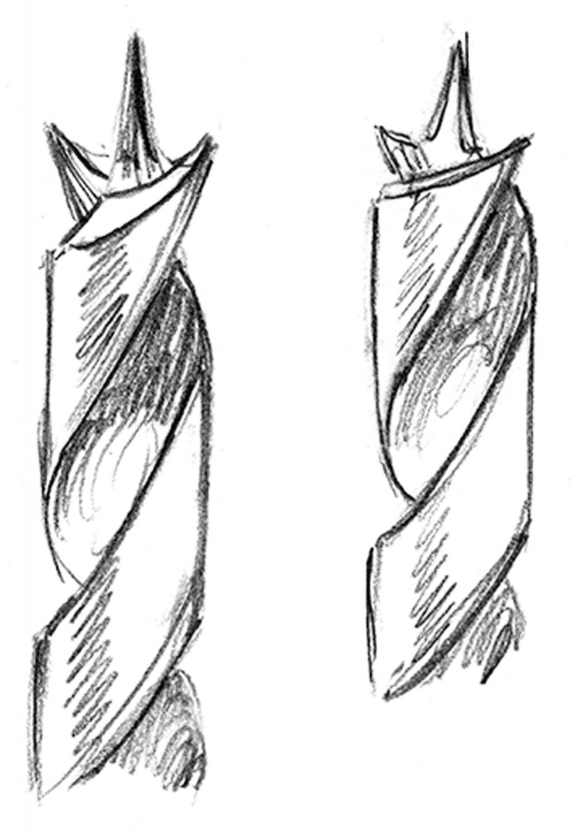
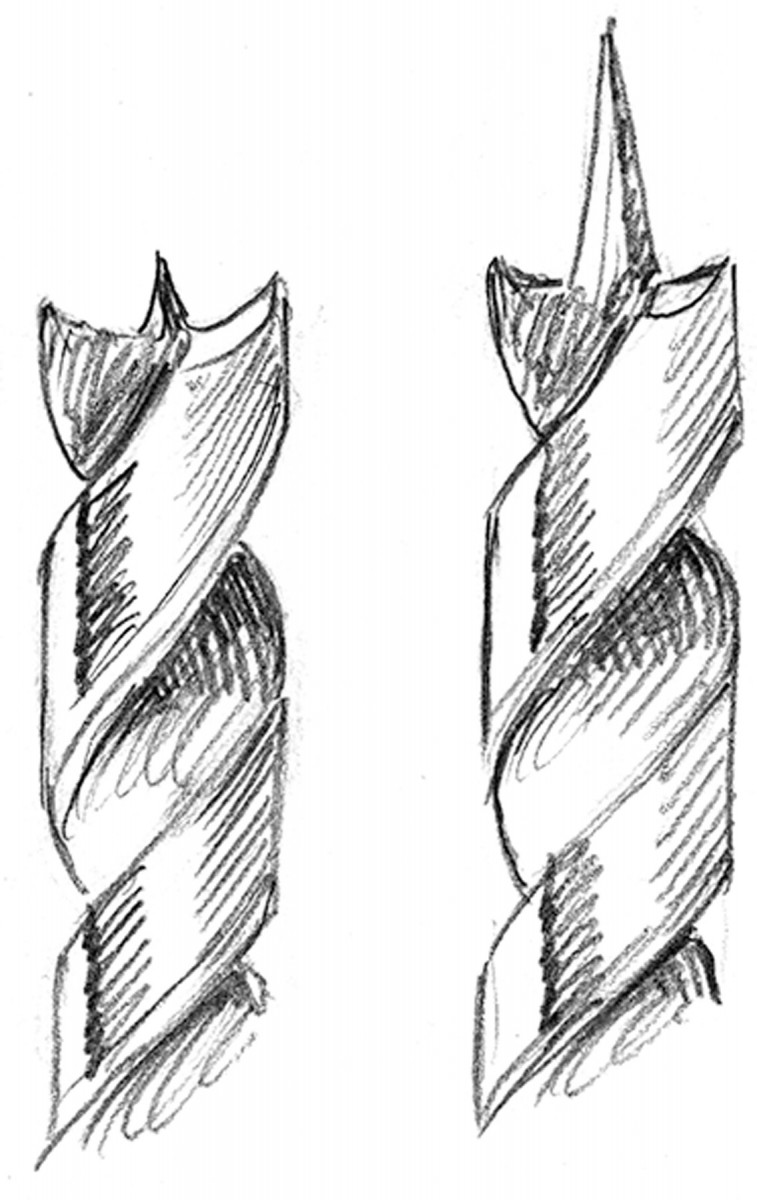
Steep for hardwoods (left), Shallow for softwoods (right).
For the first cuts to establish the wings, rotate the bit until the cutting edges are horizontal.
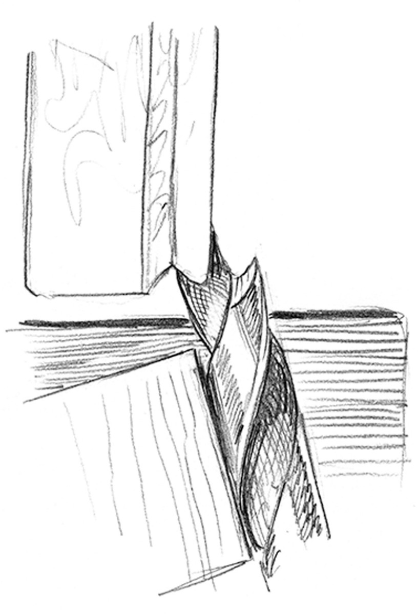
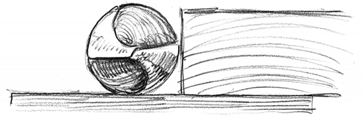
1. Push the bit into the wheel to establish one wing. To the point. The first cuts on the bit form the brad point.
2. Rotate it 180° to cut the other wing.
Moving the fence left or right will give a longer or shorter lead spur.
Another factor that determines the function of the bit is the angle that the tool rest is set and the resulting relief behind the cutting edge. I measured the angle of a bit that I used for most tasks and found it to be about 35°. The steeper the angle, the more aggressive the bit; at some point, the edge is too thin to be effective. I always use high-speed steel because it doesn’t lose its temper until it is red hot, so a little bluing is fine.
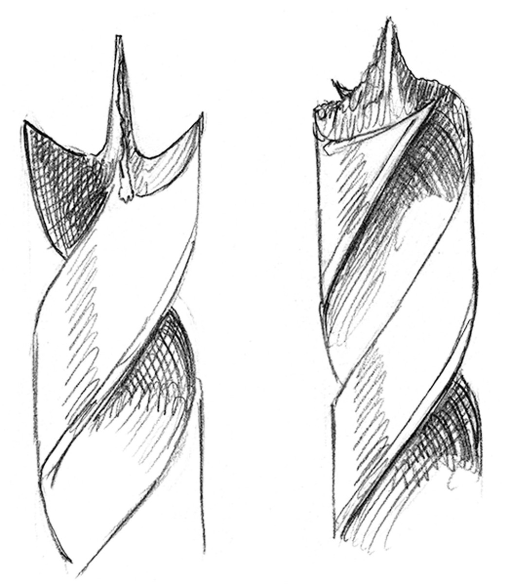
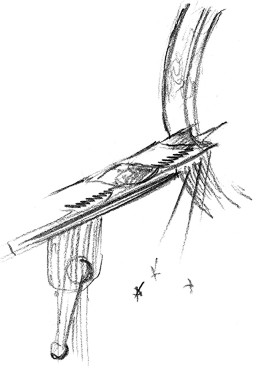
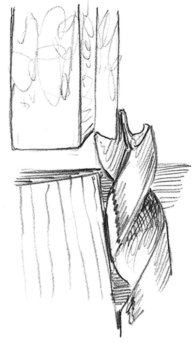
1. After the wings are ground, there will be a thin web of material in the other plane. Rotate the bit 90° to see the web.
2. Put the bit back on the tool rest and this time rotate the bit so that the cutting edges are vertical.
At right is the jig setup that I use while grinding. The simple wood fence positions the bit about 4° off the axis of the wheel. As you can see, it is the side of the wheel that actually forms the center point. By adjusting the location that I clamp the block to the rest, I can adjust the length of the bit’s center point. The farther that the fence is to the right, the longer the center point will be.
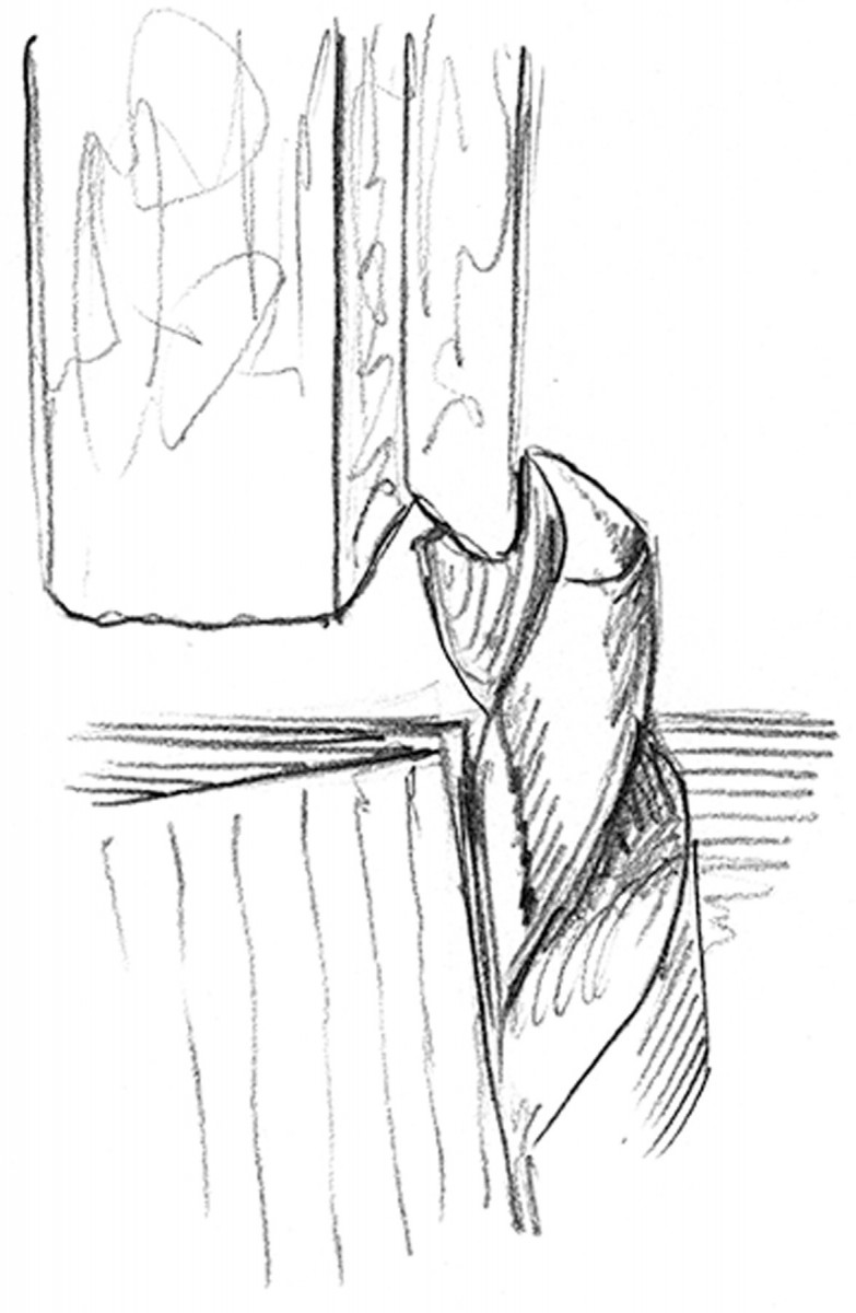
3. Push the bit into the wheel the same as when grinding the wings, but at the end of the cut, let the bit come slightly off the fence.
De-web. At right is the bit with the wings ground. All that remains is to remove the web (you can see it in the center of the bit) that has been left by the grinding.
Below is the first cut. I make sure that the existing cutting edge is horizontal and proceed to grind. After a moment, I judge whether the position of the fence is set correctly (left to right) to form the proper point. Of course it’s better to have the point be too fat and long because it’s simple to move the fence left to remove more material.
4. Extra care must be taken not to let the bottom spur contact the wheel and make a flat spot.
Once the wings are formed, you will notice a thin sheet of metal on the parts of the bit that were vertical during the grinding process. I call these webbing. These are removed using the same setup as the wings, but have a couple of other concerns to be aware of. To start grinding, position the webbing so that it is now in the horizontal position that the cutting edges were in the first step.
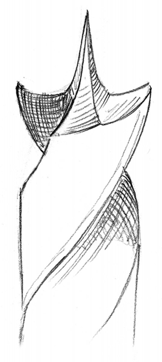
5. Then grind where the webbing was.
The tricky part about grinding away the wings left by grinding the center point is that the wing that is pointing down is dangerously close to the grinding wheel and the slightest encounter will send you back to the beginning. It’s not a big deal, but it’s better avoided. I avoid hitting it by keeping the wing that is pointing up a little past vertical (toward the grinding wheel). By keeping the wing that I can easily see close to the grinding wheel, I can generally keep the other one in the clear. The other key to grinding the web is that as I proceed to push the bit into the wheel, I let it come off of the block a bit. This happens quite naturally because as I push into the wheel, the amount of metal that is cut gets greater and the bit wants to slide to the side. You can see the result of this in the drawing numbered 3 below.
—Excerpted from “Chairmaker’s Notebook,”
by Peter Galbert (Lost Art Press)
Drill
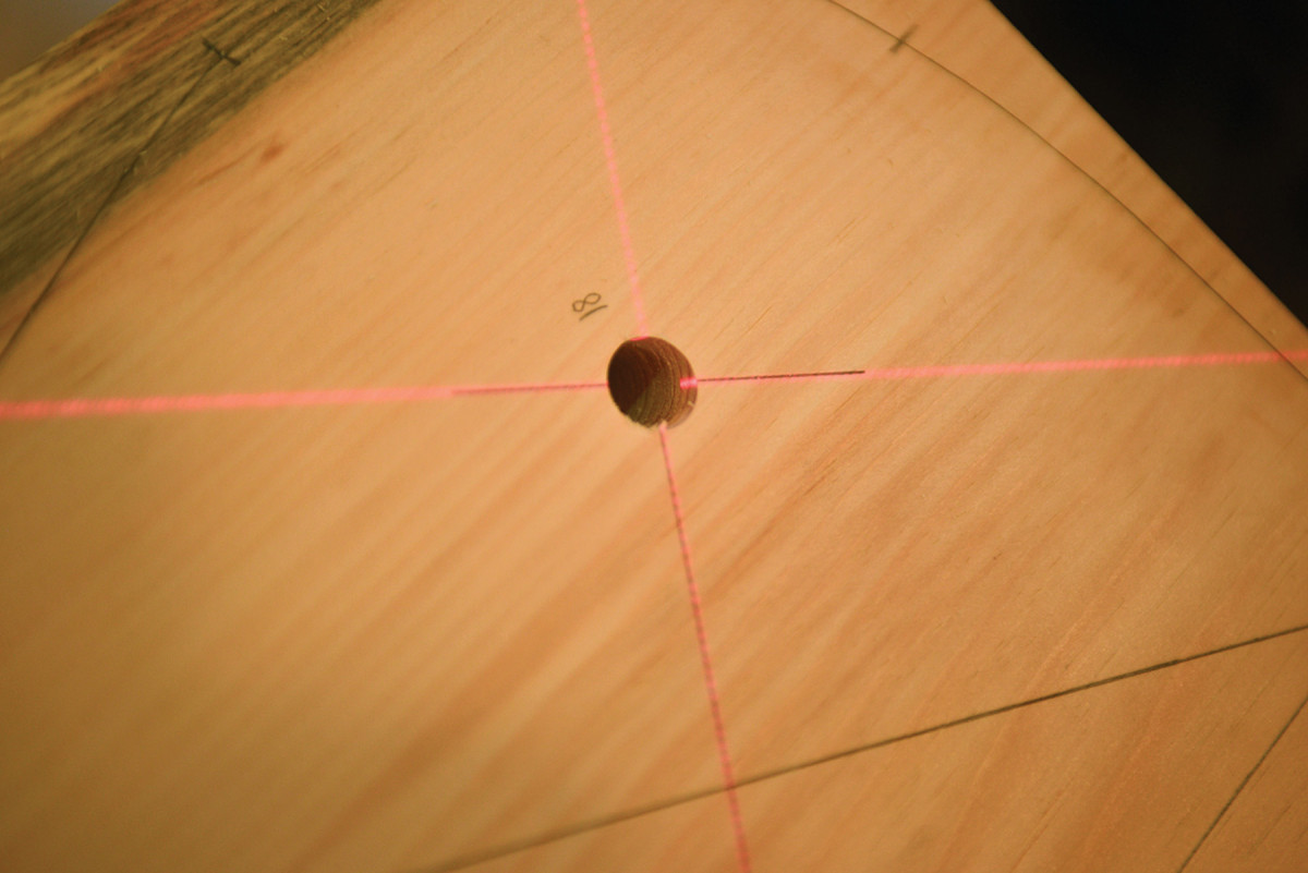
Lay out the seat pattern. Use the lasers to create a crosshatch at the angle your drill will follow down the hole.
I use a grind on the tip of my high-speed steel twist bits to give me a long lead point. This creates clean holes and allows lots of freedom to lean the drill for angles without the bit walking across the wood. See “Grinding Drill Bits” to learn how to achieve this grind yourself.
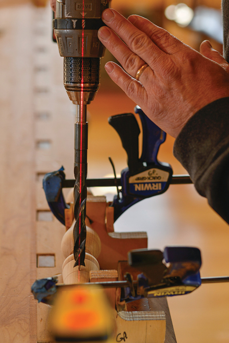
Bull’s eye. Use the drill’s casing to find the center axis of your bit.
I use the drill’s casing to help find the center axis of the bit while drilling. You can also draw or create a bull’s-eye on the back of the drill to find center.
Now line up on your crosshatch and pull the trigger. If you do not hear me mention anything else, remember this phrase: “High speed, slow feed.” The drill bit must enter clean at full cordless-drill speed while holding back its full weight and power all the way through the hole. Trust me, this will make much happier holes. Think of it as full throttle on your car while standing on the brake: great control. Practice in scrap wood to get the feel. Finish the hole while watching the crosshatch the whole time. It gets easier each time you perform this operation.
Reaming
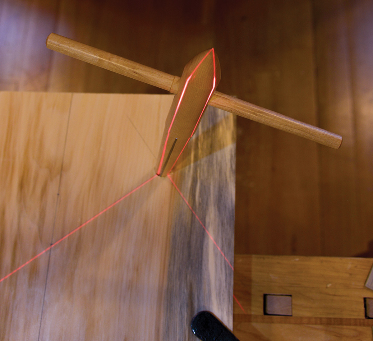
The perfect ream. Laser-guided reaming can correct misdrilling by setting the perfect rake and splay. Note the crosshatch on the top of the reamer.
The accuracy you achieve drilling with lasers is amazing and simple. It’s a confidence builder. But the true magic in Windsor-chair construction is the tapered, reamed leg and arm joint. Laser-guided reaming can fine-tune any misdrilled hole to perfect rake and splay. The setup is exactly the same as drilling straight holes, but a benefit of hand-powered reaming is greater control in each turn, while still being able to easily see the crosshatch on the reamer’s top. Every twist can perfect your alignment. And while perfection isn’t critical on a regular chair, for rockers it’s beneficial to keep things the same on each side. Same goes for stools with a box stretcher design – balance keeps the box nice and square.
What’s Next?
The perfect ream. Laser-guided reaming can correct misdrilling by setting the perfect rake and splay. Note the crosshatch on the top of the reamer.
Now that you’ve drilled and reamed holes with lasers, what else can you do? How about finding true center of a chair before drilling the back? Just set the laser down the center of the seat positioned 90° to the surface, dividing the chair in two – true center. It floats a line nicely across everything that crosses its path.
Lasers are also handy for finding the center axis of legs and stretchers when drilling. Just shoot the laser from one drive center to the other on the turning, and it indicates at which point to place the tip of the drill, and helps keep the drill perpendicular.
There are many more areas of use waiting to be explored, and I seriously hope you give lasers a try. They may not be for everybody, but a couple of lasers are not a big investment – if you don’t like them, just pass them on to a friend. Happy drilling!
Here are some supplies and tools we find essential in our everyday work around the shop. We may receive a commission from sales referred by our links; however, we have carefully selected these products for their usefulness and quality.


