We may receive a commission when you use our affiliate links. However, this does not impact our recommendations.
My last several posts have been about how the BARN workbench vise chops were designed. In this post, I’ll show you how the CNC was programmed for machining with CAM software. I use RhinoCAM software from MecSoft, but most CAM software programs that can handle basic 3D milling will have similar machining operations.
This post is not a primary on CAM or a full explanation of all the settings that were used; just an overview of my approach to 3D carving this project. Also, I’m skipping the design, programming, and milling details of the large pocket on the backside of the vise for the Benchcrafted Criss Cross mechanism and the large through-hole for the vise screw. I’ll cover these processes at another time. This post is just about setting up for 3D carving for the face of the workbench vise chops.
Roll and Tuck
Roll and Tuck
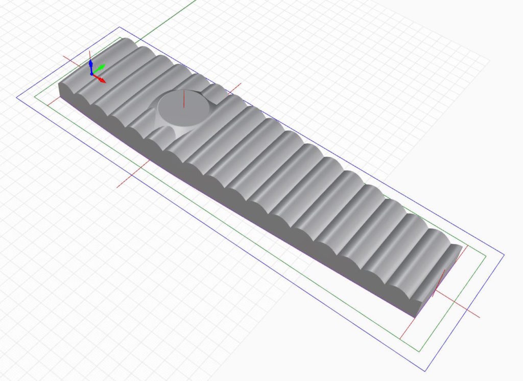
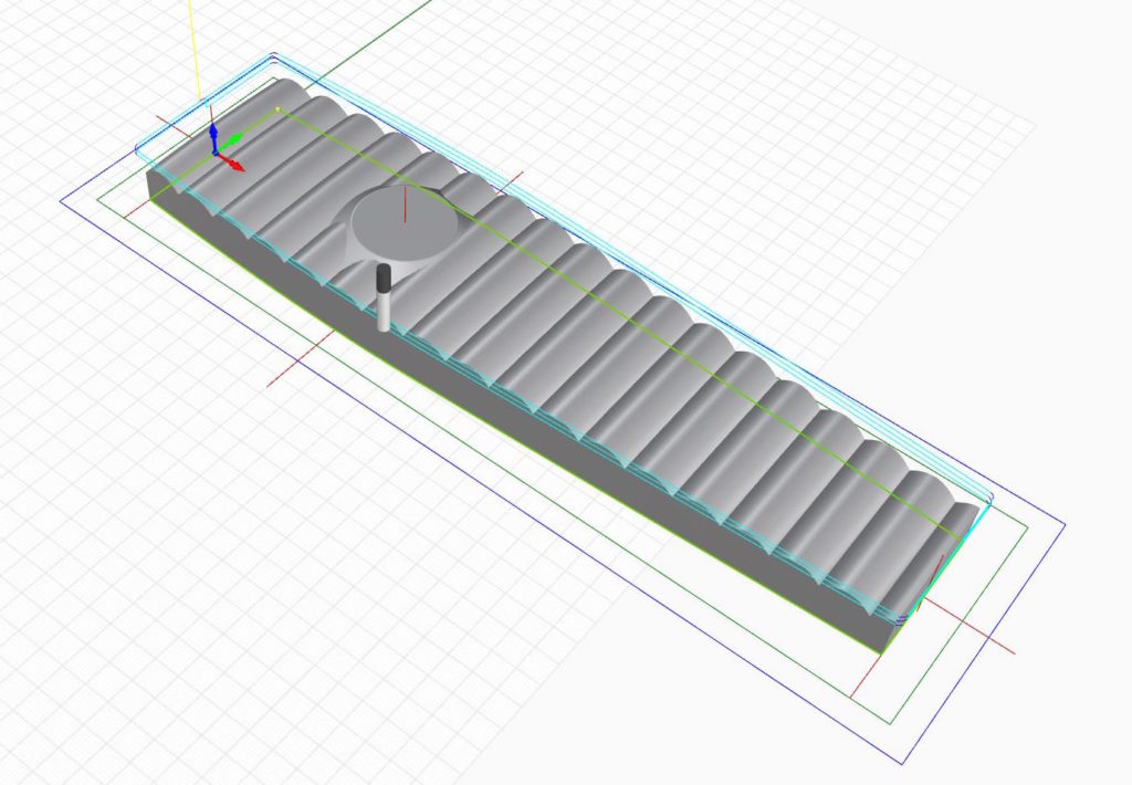
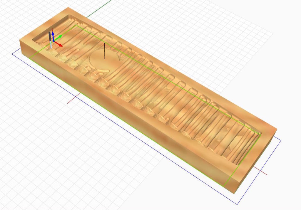
The Roll and Tuck vice chop inside the 36″ x 10″ x 2.75″ block it will be carved from.
This vise design was one of the simplest of the set to create in CAD. The goal was to simulate roll and tuck upholstery in maple. I just created a series of semi-circles and connected the ends. Once I had enough to cover the length of the vise, I extruded them to make the tuck and roll surface. Like all the other vise chops, to soften the shape, I warped the result onto the gently curved base surface and trimmed the excess. Above is the final 3D model and how it sits inside the blank stock I’m going to be milling from.
Profile or Contour Cutting First
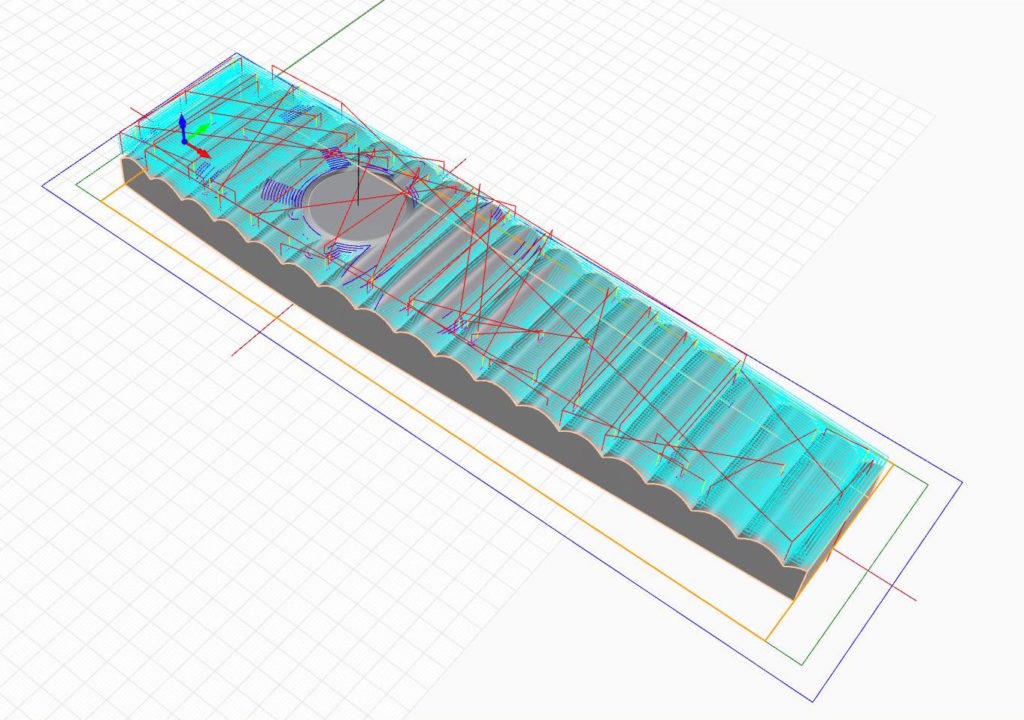
Profile or contour cutting is the CAM process used for programming a CNC to cut out parts. Essentially, it’s an operation to send the spindle around the perimeter of the part you want to cut out. This is a screen capture from the simulation I used to verify my programming before actual cutting. The tool paths are shown in cyan blue, the cutter is shown on the side of the vise chop.
Pro tip: At some point, you need to cut the part out of the blank material you start with. When I do detail 3D carving that’s right up to the edge of the piece, I sometimes machine the outside of the piece first through a process called Profile or Contour cutting. When cutting the outside of the part I leave tabs or bridges so that the cut piece is still connected to the remaining stock material.
Now, that might seem a bit odd to do the last thing first, but there are good reasons to do it. If I clear off the wood that’s around the outside of the final piece, unnecessary wood won’t be in the way of the more delicate 3D final carving process I’ll use at the end. This is a particularly important technique when using smaller ball mills like I do for my final 3D carving passes. Also, I run my final passes at very high speeds and yes, I have broken a few bits when they dropped down near an edge, cut too deep into the wood and snapped. Sometimes it’s just simpler to remove the wood that you know needs to go sooner, rather than later to eliminate potential problems.
Next, Remove the Excess
A horizontal roughing pass is done layer-by-layer. Hard to see in this capture, but there are a dozen layers, here. Where the spindle moves from one position to the next around the chop is shown by the red lines.
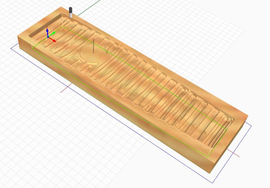
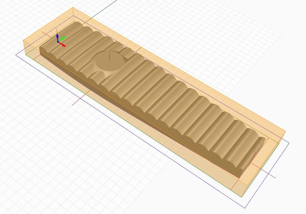
Similar to a 3D topographic map, this roughing pass removes most of the material. The result is the milling looks pretty much exactly like what’s shown above.
With a lot of wood to remove off the surface for 3D milling, it’s best to clear off as much wood as possible first. I used a roughing process that removes wood layer-by-layer with a .500 bit. In RhinoCAM it’s called Horizontal Roughing. The results are similar to a topographic map. I left about .030″ extra wood for the final pass. Shown above are the tool paths and a simulated carved result.
Here’s a short video of one of the other vise chops being rough cut on a CNC…
A final pass brings out the details and leaves a smooth touch
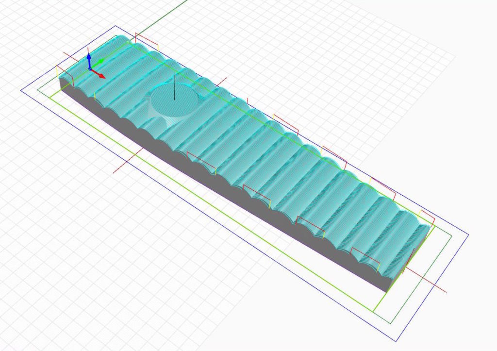
A parallel finishing pass travels the length of the design moving back and forth and up and down following the contours of the 3D CAD design.
The near side of this capture is showing the simulated final parallel run working its way through the rough cut that was done in the previous step.
Now it’s time to CNC carve the fine details. For this particular piece, I chose to use a process called Parallel Finishing and a .250 ball mill. This sends the cutter along the entire length of the chop, moving up and down following the roll and tuck shape. Once the spindle reaches the end of the run, it moves over a little and cuts another row and so on until it’s covered the entire piece. Just like moving a really large lawn, it can take quite a while.
A Final Reveal
Over seven posts, we’ve covered the basics on how the BARN bench vise chops were designed, drawn in CAD and milled on a CNC. Now that the project is done, I have a confession: There’s a reason I went into all the detail on creating these workbench vise chops. If you’ve patiently held on and read all the posts and seen the final results, the reason is something of a bonus. Though they turned out very nice, this was never really about vise chops. This series is really a primer on creating 3D carved surfaces with shape and pattern in wood.
If you’ve been reading this column regularly, it’s likely because you’re curious about digital woodworking. The big question on everyone’s mind is what can be done with these tools? This series answers part of that question by showing an important potential and should leave you with quite a bit to think about. If you’re a furniture maker — hobbyist or pro, and serious about mastering your craft and willing to really learn how to design, then digital tools are very powerful creative tools. They can take you and the pieces that you make far beyond flat surfaces into the exciting world of 3D shaping, carving, and patterns.
So, I just gave you a really big reveal. If you want to take that next big step forward in furniture design here’s the secret: Combine the traditional woodworking craftsmanship we all love with digital woodworking tools and good design skills. It’s a killer combo that takes furniture making into exciting new directions. Stay tuned.
Also, a note that I’m teaching a hands-on class on these and other intermediate and advanced techniques at the Marc Adams School of Woodworking in Indiana on October 1st. Good choice if you’ve already started using CAD and ready to get moving on getting the best out of a CNC. The class is about digital woodworking skills and techniques in CAD, CAM, and CNCs and using these new tools along side traditional woodworking methods. A few openings are left.
Finally, regarding the BARN Workbench, I’ll do a future post on how the dogs holes on the top of workbench were laid out in a way to make traditional hand tool woodworking a bit more comfortable to do. Told you that using a CNC to make a hand tool workbench is a little different. And, a post showing the final 9 workbenches in their new home.
Additional Resources
- All posts on the BARN workbench click here.
- Photos of the BARN workbench chops click here.
- A video about how the chops were made click here
- Additional Digital Woodworking videos click here.
Here are some supplies and tools we find essential in our everyday work around the shop. We may receive a commission from sales referred by our links; however, we have carefully selected these products for their usefulness and quality.