We may receive a commission when you use our affiliate links. However, this does not impact our recommendations.
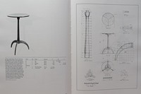
 In Part 1 we modeled the Pedestal but didn’t include the dovetail sockets to receive the legs. In this post we will add the sockets. Click on the image at left to see an enlarged view of the 2D drawing provided by John Kassay. On the right hand page, in it’s lower left-hand corner, just above the scale, you will see the details for the socket.
 They will be almost impossible to read in this image; I had to use a magnifying glass to read some of the measurements in the book. Fortunately you have me and SketchUp to provide them; enlarge the image at right to see the details as described in the book.
NOTE: The remaining steps must be performed with the Pedestal in Edit Component mode. Choose Camera/Parallel Projection and Camera/Standard Views/Bottom. Draw one socket at a time or the construction lines will get too confusing. The image above right shows only one socket drawn, but center lines and guide points for all three.
First thing to realize is that this stand has three legs and therefore they are equally spaced 120° apart. The second observation should be that SketchUp does not draw circles; it draws an approximation using equal line segments. By default there are 24 segments. You can change this parameter to any number you want, but I have used the default of 24 in this model. If there are 24 segments in total, then there are 8 segments in 1/3 the circumference; 120°/360°. Center lines for the sockets can be located by drawing a construction line from the center of the circle (origin in this case) to each eighth Endpoint of the circle segments. There will be three center lines intersecting Endpoints. At each Endpoint draw a construction line terminated with a guide point along these center lines and toward the center of the circle, each 9/16” long. Repeat this step, but in this case away from the circle center, along the center line and 11/16” long (1 1/4” – 9/16”).
Using the Protractor tool, draw a construction line perpendicular to the socket center lines and passing through the guide point nearest the circle center. Use the Protractor tool to draw a construction line passing through the guide point farthest from the circle center and 14° to its right. Repeat this step with a line 14° to the left. This creates two construction lines 28° apart and centered around the center lines.
 Use the Line tool to draw the side and end lines of the socket beginning at the intersection of the 31/32” circle and a construction line to the left of the center line, connected to the perpendicular intersection of this line, connected to the intersection of the perpendicular and the right construction line and terminating at the intersection of the 31/32” circle and the construction line to the right of the center line. Use the Push/Pull tool to push the socket in to the bottom most plane of the 1” circle. Erase the two inside unwanted remnants of the 31/32” circle.
After repeating the above on each socket exit Edit Component mode. The image above left shows the completed sockets. To download the SketchUp file used in this post click on this link. In Part 3 we will model the legs. See you then.
Here are some supplies and tools we find essential in our everyday work around the shop. We may receive a commission from sales referred by our links; however, we have carefully selected these products for their usefulness and quality.


