We may receive a commission when you use our affiliate links. However, this does not impact our recommendations.
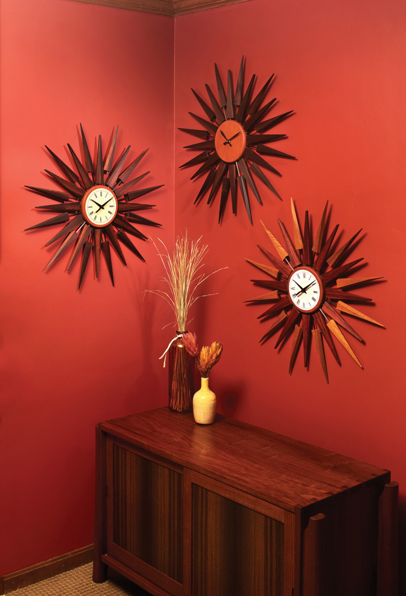
This modern take on a mid-century classic is a study in precision geometry.
The sunburst-style wall clock came in a variety of shapes and sizes during its heyday of the mid-1940s to the mid ’60s. Its aesthetic captured many of the design elements common to the mid-century modern style – curves, colors, acute angles and mixed materials – all elegantly arranged to deliver both beautiful design and function. Designers such as George Nelson with his work for the Howard Miller Clock Company (the iconic polygon clock), as well as his imitators, followed a simple set of three structural elements.
The first is the central structure of the clock face – usually round, and either painted or adorned with a printed metal face of Arabic or Roman numerals, and, of course, the hands of the clock. Next are the spokes, typically round brass rods extending outward in a concentric pattern, and numbering anywhere from as few as four to as many as 48. Then come the rays that connect to the spokes; they often resembled sunflower petals, sun rays, globes or diamonds, and were commonly made from teak, walnut and rosewood.
These three key elements form the basis of just about all of the mid-century modern clocks that were produced last century, and they are replicated today. They also provide the baseline for developing an almost endless number of styles and variations. The version I’ve built here measures 30″ in diameter, has 24 rays and uses Brazilian rosewood and carbon-fiber tubes – an updated look to the traditional brass.
Design at Full Scale
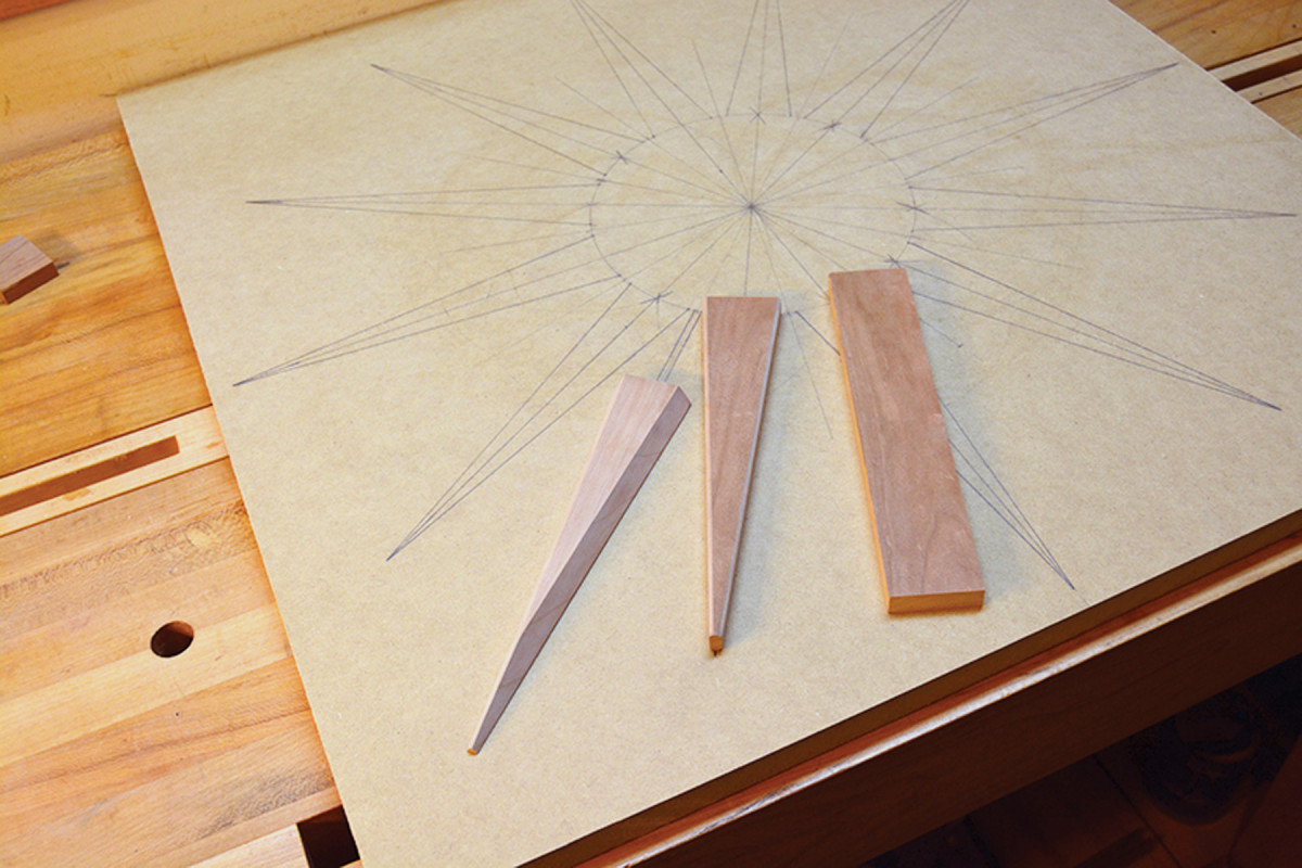
Out of one, many. Working from a scale drawing and common-sized stock materials offers a variety of design options for the final shapes of the rays.
The great part about the sunburst design is that by alternating the number and geometric shapes of the rays, as well as the lengths of the spokes connecting them to the central dial, you can come up with a wide range of variations. My goal was to make two styles of rays efficiently by using the same dimensioned blanks for each style: 1⁄2” x 1 9⁄16” x 8″. The inner rays are a straightforward triangle shape, while the outer rays have complex bevels on the triangle sides for added visual interest.
The rays were the perfect place to use some (pre-embargo) Brazilian rosewood I’d been saving for a special project. (Black walnut would also be a good choice.)
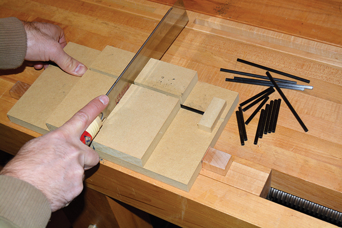
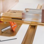
Consistent cuts. A small jig made from MDF holds the tubes in place, and a fine-toothed dozuki saw ensures consistent and square cuts on the tough carbon fiber.
To get started, mill the 24 rectangular ray blanks – and make a few extras from scrap wood to use for test cuts. The blanks should be ripped from quartersawn material so you have straight grain on all the rays.
In the period, the rods were typically made from brass – and you can certainly use that for your project. This design, however, uses a far sturdier and lightweight option: 5⁄32“-diameter carbon-fiber tubes. To match my design, you’ll need 12 pieces at 2 1⁄4” long, and 12 pieces at 5 1⁄2” long. A modified bench hook (above) helps you make consistent cuts. Chamfer the ends of the rods with #220-grit sandpaper to make them slide more easily in the holes.
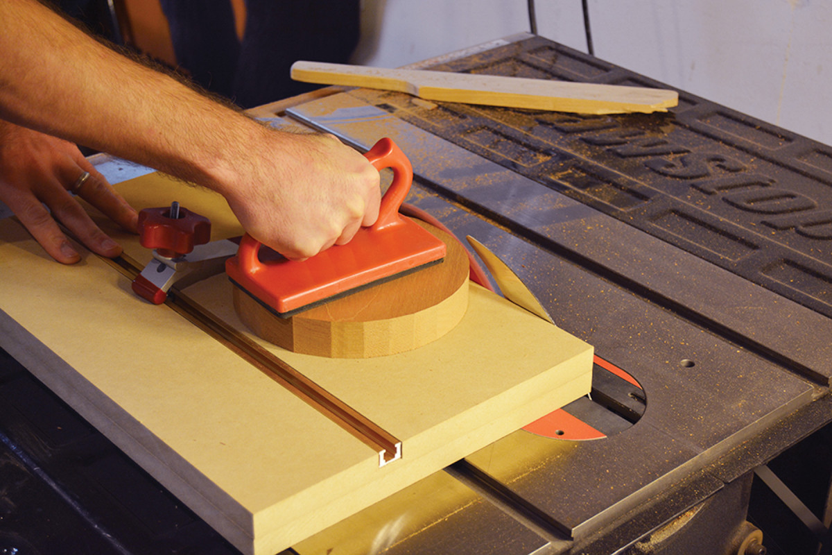
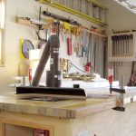
Table saw circles. I cut circles on the table saw using a sled and clamp. The stock is positioned on a small pin centered 31⁄2″ from the blade (the circle’s radius). Clamp the face, cut a facet, then rotate the piece several degrees for each successive pass to approximate a complete circle.
For the clock face, I chose Honduran mahogany. Use whatever method and tools you prefer to cut a 19⁄16“-thick x 7”-diameter circle, then drill a 5⁄16” hole through the center. Sand the edges fair and smooth with #220 then #320 grit wrapped around a block that matches the radius of the circle.
Precision Matters
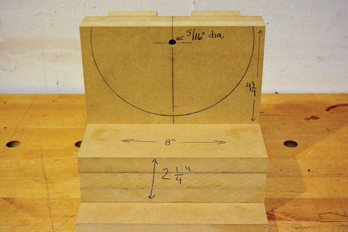
One jig, two uses. One side of the jig (above) holds the face in position at the drill press; the other side (below) holds the ray blanks.
 Precision is a must with this project, so making many accurate geometric pieces requires some unique but simple jigs. If you stray from this particular design, you’ll need to make the appropriate adjustments on the jigs to accommodate your clock’s geometry.
The first is the aforementioned jig for the carbon-fiber tubes. The next one (below), serves two purposes on the drill press:
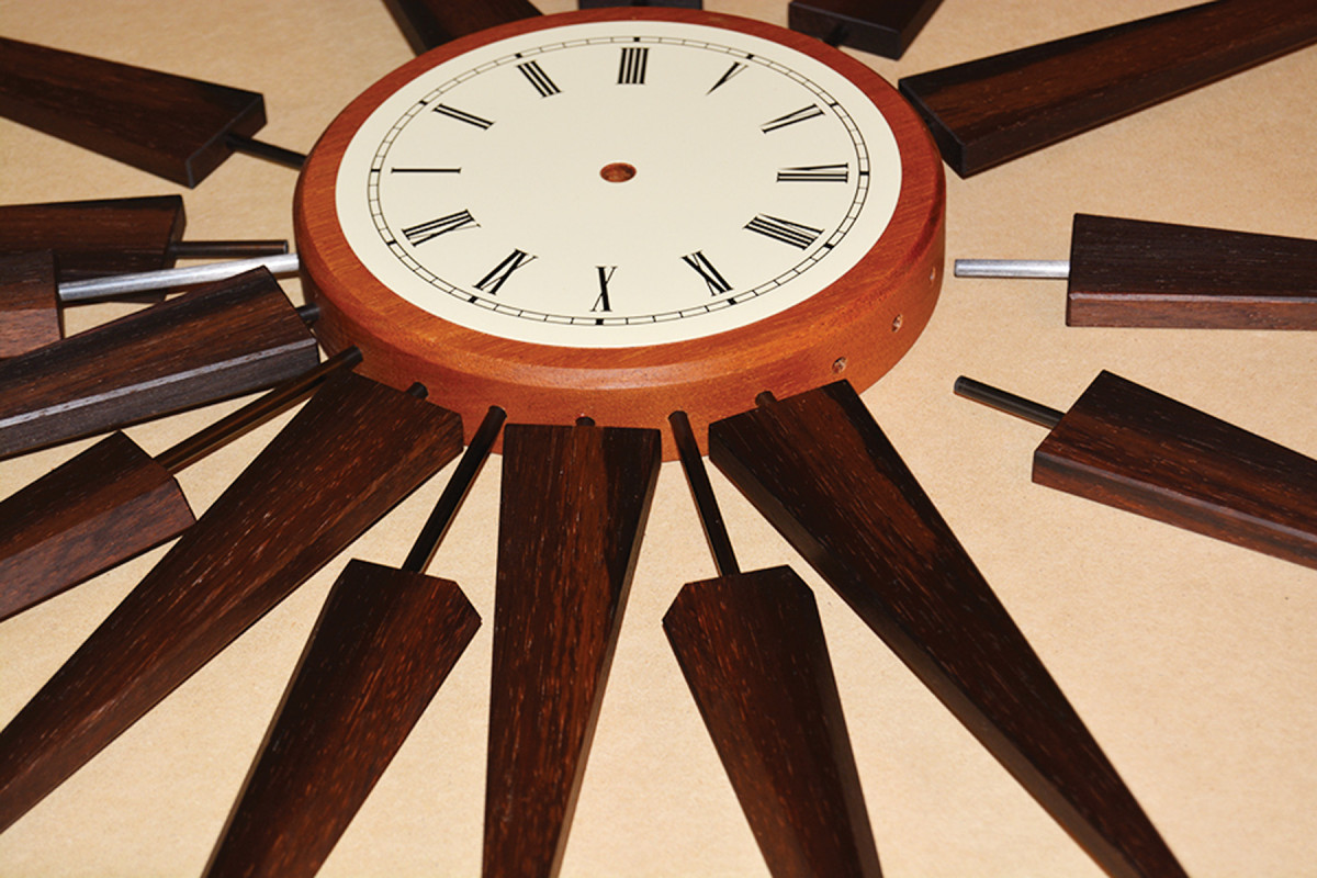
You’ll need to affix the clock dial to the jig using a 5⁄16“-diameter shaft in the dial’s center hole (I used a 5⁄16” drill bit) to provide precise vertical and concentric alignment of the 24 rods that connect the dial to the ray pieces.
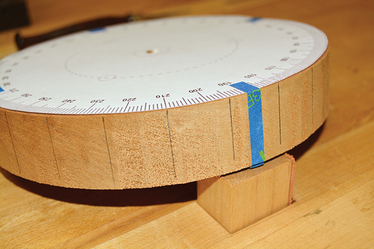
Paper template. Mount a 7″-diameter paper compass printout to the clock dial so you can squarely mark out the location of each of the 24 holes on the outside edge of the face, each spaced at 15° increments.
After you’ve marked the hole locations, mount the face to the jig, and secure the jig to the drill press to drill 1″-deep x 5⁄16“-diameter holes directly in the center of the face’s thickness at each of the 24 marks. So that each hole is oriented properly along the face’s radius lines, use a square to ensure the 5⁄16” center pin is directly in line with the travel of the quill
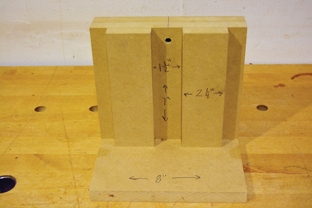
Now turn the jig around to drill the 1″-deep holes in the ray blanks. Again, take care each hole is exactly centered on the end face and parallel to the blank’s centerline.
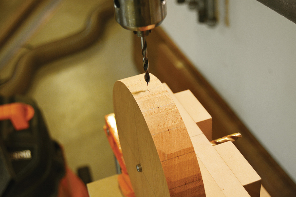
Precise holes. Moving around the dial, drill all 24 holes with a brad-point bit. Accuracy matters, so be sure to hit as close to the middle of the line as you can.
With the drilling done, complete the clock face by routing a 1⁄16” chamfer on the back edge and a 3⁄8” chamfer on the front edge.
You’ll also need to inset the clock movement on the face’s back. To locate it, cut a scrap piece slightly larger than your movement and drill a centered 5⁄16” hole. Use a drill bit to align the location as you orient the movement with the vertical grain of the face. Then remove the waste. (For my movement, a 23⁄16“-square x 3⁄4“-deep recess was required, including a bit of wiggle room for easy access for battery changes.)
Now drill the holes in the ray blanks.
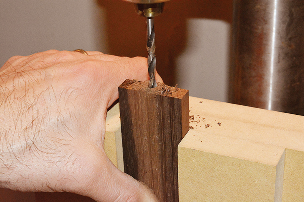
End runs. Made from MDF scraps, this simple yet sturdy jig helps align the ray blanks to ensure accurate drilling for the carbon-fiber tubes.
To cut the rays to their final shape, you’ll need two more jigs; see “The Rays: Precision Geometry” at right. And I recommend you first make some practice cuts on inexpensive scrap wood before tackling any expensive stock.
Sunburst Wall Clock Cut List
No.ItemDimensions (inches)MaterialComments
t w l
❏ 24 Ray blanks 1⁄2 x 1 9⁄16 x 8 Rosewood Cut extra for test cuts
❏ 1 Clock face 19⁄16 x 7 dia. Mahogany
Finishing Up
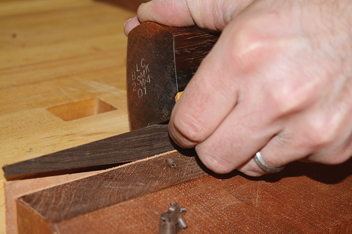
Vise work. Planing small pieces can be tricky; keep them securely clamped and keep your fingers away from the sharp edges. For the acute-angled outer rays, plane gently as you approach the points.
With all of the pieces cut, plane the edges smooth. A few passes should do it.
Next, move onto #220- and #320-grit sanding. I secured a piece of sandpaper to a sheet of plate glass and “polished” each surface much like a jeweler polishes the facets of a gemstone.
Finally, apply two coats of Watco Teak or Danish oil (avoid getting too much oil in the rod holes), then apply a finishing wax.
Now oil the clock dial (again, try not to get much in the rod holes). Wax all surfaces but the face.
Next, apply some cyanoacrylate (CA) glue to the back of the metal clock face and affix it to the center of the dial, taking care to align the holes at the 3, 6, 9 and 12-o’clock positions. Place a flat weight on top to hold it in place while it dries.
The Rays: Precision Geometry
 All of the rays are designed to end in a blunt point, and use a common set of angles. This is done by two simple sets of modifications to a table saw sled (or simple throw-away versions) using a pair of guide blocks and two cam-lock clamps.
To set up for the interior rays, first cut two guide blocks from 3⁄4” x 7″ x 4″ stock. On the first block, cut one long edge at a 5° angle, and on the second cut one long edge at 10°.
For the first cut, secure the 5° block to the sled (to the left of the blade slot) such that when a ray blank is secured to it, the near right corner of the blank falls exactly at the intersection of the blade slot and the sled’s main fence. (The guide block will meet the sled fence just a bit more than 19⁄16” from the left of the slot.)
Finally, attach one of the surface clamps to the block to secure blanks for this cut. The 10° block is a bit simpler to position; it needs to be placed such that its rear left corner meets the fence precisely 19⁄16” from the right edge of the blade slot. Attach the other clamp to the 10° block for the second set of cuts.

Outer Ray (Left) Inner Ray (Right)
This is all much easier to do than describe – but take your time here because precision and consistency are critical to the final appearance.
Place a test ray blank on the jig tight against the 5° block with the blank’s drilled hole facing toward you. Clamp the blank and run the sled through the saw.
For the second cut, flip the test blank lengthwise, and place it to the right of the blade slot. Use the 10° block’s clamp fixture to secure the blank and take a pass on the saw. If everything has been set up correctly, the drilled end of the blank should still be full-width at 19⁄16“, with 5° tapers up each edge to the far end, and have a blunt at the end of about 1⁄8“-3⁄16“. Adjust the setup if necessary, and cut the 12 inner rays.
For the outer rays, the jig is essentially the same, but the table saw blade is tilted 30°. Because of the sled thickness, tilting the blade will also shift the blade’s slot in the direction of the tilt (by about 7⁄16” for a 3⁄4“-thick sled base).
To compensate for this, shift each guide block to the left accordingly. You can either take a pass with the sled first, then use the new slot to reposition the blocks, or make a second sled if you don’t wish to sacrifice the integrity of the 90° sled. Once the guide blocks have been repositioned, use another test blank to check setup and proceed exactly as with the outer rays.
— AB
Assembly
Not suitable for small children. Assembling this clock reminded me of Tinkertoys – but with deadly sharp points. To make assembly easy, work on a large flat surface that provides plenty of room to rotate your project as you keep the backs of the rays coplanar to the work surface and parallel to each other.
Apply a small amount of CA glue in each hole of the 12 inner rays and slide in place the 2 1⁄4“-long rods. Repeat this step with the 5 1⁄4“-long rods on the outer rays.
Once the glue is dry on the face rods, alternately glue up the inner and outer rays around the circumference. Be sure to make the rays’ surface coplanar with the face of the clock; small deviations add up visually.
Finally, attach a picture hook to the back of the clock about 3⁄4” down from the 12-o’clock position and assemble the clock’s mechanical movement to the clock dial, following the manufacturer’s instructions.
Now it’s just a matter of installing a battery, setting the time and hanging your clock in a prominent place to add a little mid-century modern flair to your home.
Plan: Download a free SketchUp model of this project.
Supplies
McMaster-Carr Rigid carbon-fiber tubes, .188″ OD
ClockParts.com
1 ■ 6″ Ivory clock dial (roman)
1 ■ Clock hands set
1 ■ Mini quartz movement
Here are some supplies and tools we find essential in our everyday work around the shop. We may receive a commission from sales referred by our links; however, we have carefully selected these products for their usefulness and quality.