We may receive a commission when you use our affiliate links. However, this does not impact our recommendations.

8146-99
Although delicate, this graceful table should provide years of service in your home.
Many years ago while teaching a chairmaking class at the Marc Adams School of Woodworking, I thanked Mario Rodriguez (who was teaching a hand-tool class at the school that same week) for writing a magazine article I had seen some years before in which simple tenons had been substituted for sliding dovetails to join the legs of a period tripod table to its pedestal. The article, I explained, had been a revelation, allowing me to simplify the construction of these tables without losing any real strength. Mario very kindly pointed out that he had not written the article, nor did he know who had.
Ouch.
Despite my confusion over its authorship, the article had been a revelation, one that changed the way I built these tables and one that caused me to take a long-overdue look at the issue of joint-making excess.
Complex mechanical joints (the very best examples can be found in period Chinese furniture) offer a high degree of strength even without the use of adhesives. This strength is achieved through the use of interlocking parts which – particularly when cut by hand – require skill, patience and time to create. They’re often joints that are visually elegant and provide eloquent testimony to the furniture maker’s skills.
What I had never really considered until reading the article I had mistakenly attributed to Rodriguez is that often these constructions represent joint-making excess. This is because the mechanical strength of a joint is limited by the resistance to breakage of the wood species from which the joint is cut. This very obvious truth is sometimes overlooked by those of us who fall in love with the joint-making process. In our zeal to create elegant joinery, we – perhaps willfully – forget that a joint cut in a fragile species will fail when the wood fails regardless of the mechanical complexity of the joint.
I work primarily in figured maple and cherry because these are the woods my customers prefer. They’re not, however, among the strongest American hardwoods. This is a fact I put to the test many years ago using a collection of chairs I had made but had not offered for sale because of unsightly blemishes in the material. Several were built from cherry, several from figured maple, several from straight-grained hard maple, one from walnut and one from ash. To test the strength of each species, I smashed each chair against the concrete-block wall of my shop. I threw each into the air and allowed it to crash onto the driveway. I tried to drive the heel of my work boot down through the front ladder of each chair. What I learned is this: Hard maple and ash are virtually indestructible; cherry, figured maple and walnut (which fared slightly better than cherry) are not. In fact, I was astonished to see how easily I was able to destroy chairs made from the two wood species with which I most often worked.
The message was clear: Cherry and figured maple are not the woods of choice in applications requiring strength. And further, they are not ideal species to use for furniture requiring complex mechanical joinery – like the sliding dovetail – because the cherry and figured maple are likely to fail long before the elegant joinery.
The Shaker original, on which this example is based, appears in John Kassay’s magnificent volume of photos and drawings, “The Book of Shaker Furniture” (University of Massachusetts Press). As is the case with nearly all 18th and 19th century tripod tables, the legs of that original are affixed to the base through the use of sliding dovetails, this despite the fact that the original, like my reproduction, was made of cherry.
You could argue that a furniture maker would be foolish to forego a joint that holds the legs to the pedestal on the still-functional Shaker original, 150 years after its construction. However, I’d be willing to bet my wife’s shiny new car that my table – held together with lowly tenons – will still be functional in the home of my great, great, great grandchild 150 years after its construction.
Shaker Tripod Table Cutlist and Diagrams


 Preparing Materials


 Preparing Materials
I have lots of thick cherry in my shop because I often buy 12/4 material, which I then resaw for chair post blanks, but I recognize that not every furniture maker is so lucky. If necessary, the pedestal stock for this table could be glued up from two pieces of carefully matched 5/4 material.
The top on my example was glued up from two pieces of edge-jointed 3⁄4” material cut from the same board. This practice – gluing up tops from two pieces cut from the same board – is one I employ whenever I’m making small tabletops because it results in much better color and figure matching than I can achieve by edge-jointing two pieces cut from two different boards. It takes a sharp eye to see where the joint is on this top.
Because one side of that board was marred by pitch streaks, I flattened the opposite face on my jointer. Then, as soon as I had a clear surface, I ran the material through my thickness planer, removing stock from the blemished side until it had been reduced to a 9⁄16” thickness.
Turning the Pedestal
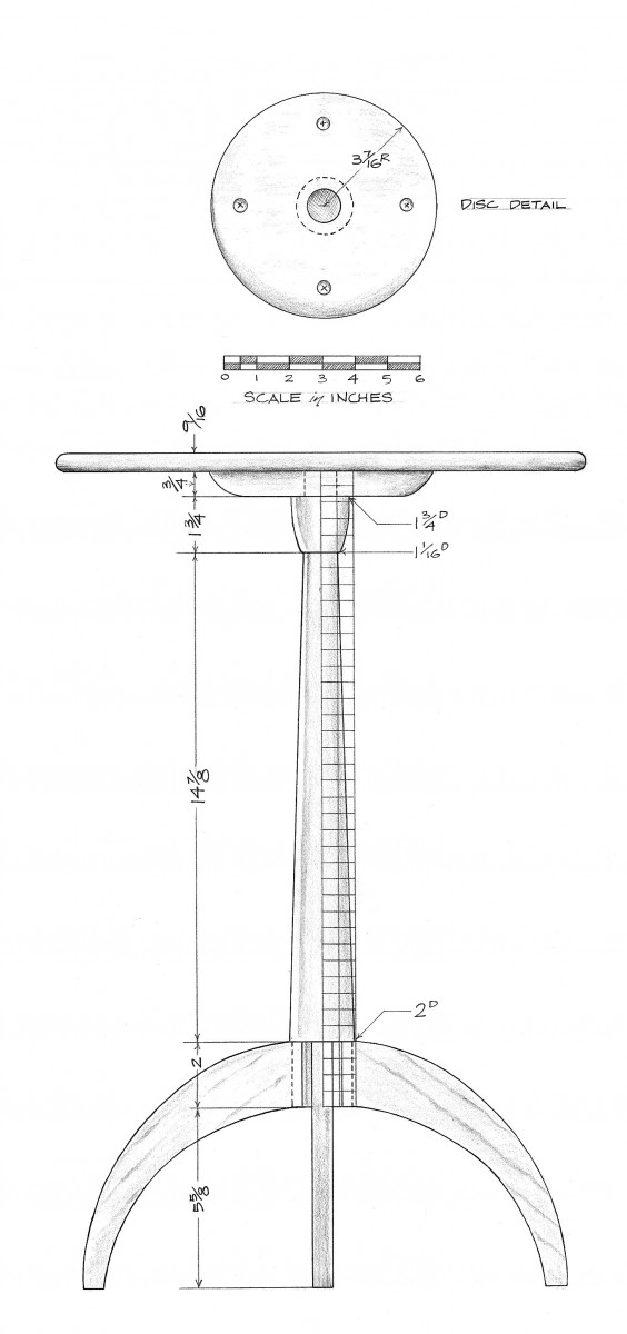
With your roughing gouge and your lathe, reduce the pedestal blank to a cylinder. Then mark the various divisions along its length. (The measurements shown in the drawing on page 79 indicate the diameters at the marked locations.)
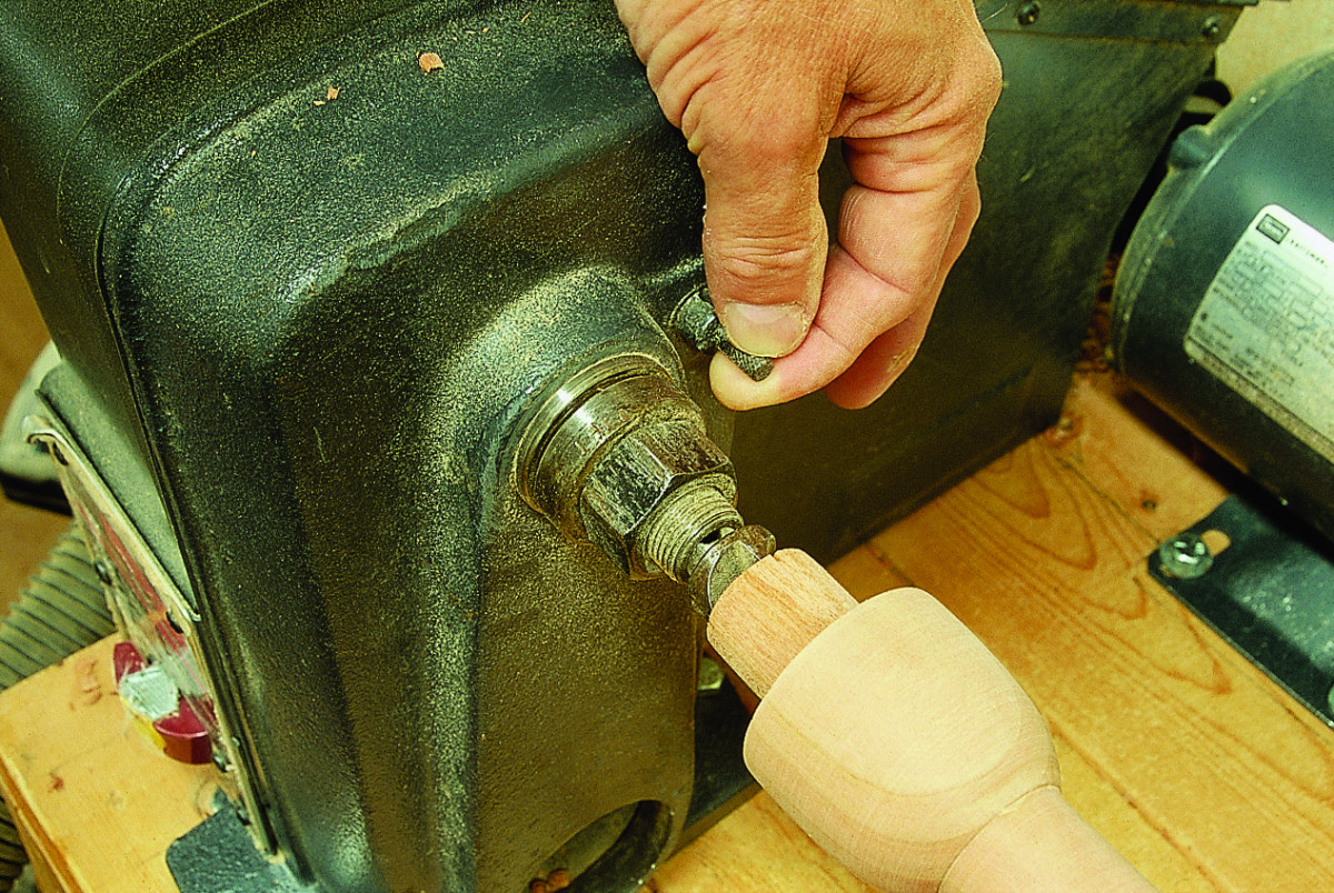
The 1″-diameter tenon at the top of the pedestal is created in two steps. First, use a fingernail gouge – 1⁄2” or 3⁄4” – to reduce the diameter so that its smallest diameter is just more than 1″. Make frequent checks of that smallest diameter with a set of calipers. Then, with a sharp butt chisel laid bevel side down, square up the outside diameter of the tenon.
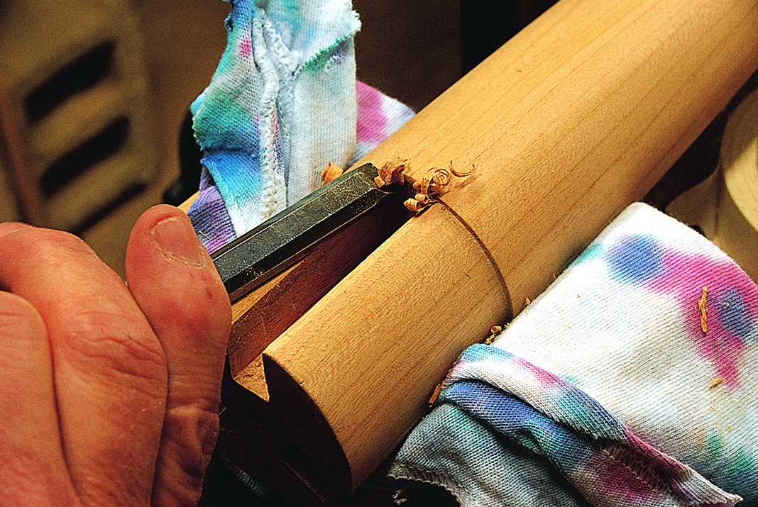
The butt chisel alone can be used to create the straight-sided 1 7⁄8“-diameter cylinder against which the legs will be fit.
Use a parting tool to set the diameter of the post where it meets the bottom of the cup. The cup can be shaped with the skew used as a plane or laid flat and used as a scraper. Then use a fingernail gouge to shape the long taper below the cup.
Tip: Mortise layout
 The leg-tenon mortises are laid out with the aide of my lathe’s indexing head.
An indexing head is a disk centered on a lathe’s axis of rotation. A number of equally spaced holes are bored near the circumference of that disk.
On my lathe, there are 36 equally spaced holes, which divide the indexing head (and any object centered on my lathe) into 36 10° increments. Increments can be counted through the use of the spring-loaded pin shown here. By retracting the pin, rotating the disk and re-engaging the pin, I can count a 10° section of an object’s circumference.
I wanted to divide the circumference of this tripod-table pedestal into three equal sections. To do that, I counted 12 stops on the indexing head, then, with my marking gauge, I drew a line along that section of the pedestal base. I repeated the process a second time, then a third time. This divided the circumference of the pedestal into three perfectly equal sections.
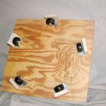
Marking Mortises
After you’ve sanded the pedestal, mark three equally spaced lines around the outside diameter of the base of the pedestal (use the tip above if possible). These three lines will mark the centers of the three mortises you’ll cut for the leg tenons.
There are several techniques you can use for dividing outside diameters into equal parts. If your lathe has an indexing head, like mine, the indexing head can be used to count off 10° increments of that outside diameter (see “Mortise Layout” at left). A set of 12 10° increments is equal to 120°, or one-third of the outside circumference of a circle.
Once the outside circumference has been divided into three equal parts, use a marking gauge – like the one shown below – to create three equally spaced lines on the surface of the pedestal base running parallel to the center of the pedestal.
This marking gauge can be made from two pieces of scrap: a vertical piece that holds the marking pencil and a horizontal piece that slides along the lathe bed. My lathe bed is a deck of 2 x 6s, so all I need is a flat block of wood for my horizontal piece (see below). If your lathe bed is a tube or a piece of angle iron, you may need to construct a slightly different horizontal piece.
Next, mark a line 3⁄16” on either side of each mortise’s center line. These lines delineate the 3⁄8” widths of the mortises you’ll cut in the pedestal base.

The lines being drawn with my marking gauge divide the circumference of the pedestal base into three equal sections. Each of these lines will become the center of a leg-tenon mortise.
Before removing the pedestal from the lathe, mark three more locations on the outside diameter of the pedestal base. These marks should be placed midway between each of the mortise center lines you created previously.
After removing the pedestal from your lathe, fix the pedestal on your bench with a pair of U-blocks and a clamp.

Fix the pedestal on your bench with a pair of U-blocks and a clamp.
Draw lines on the end grain of the pedestal base connecting the intermediate marks with the center line of the mortise on the opposite side of the base. Complete the marking process by making lines 3⁄16” on either side of the mortise center line on the pedestal’s end grain. The mortises are now completely marked.
(If you take a moment to study the photos, this marking process will quickly become clear.)
Saw and Chop the Mortises
With a fine-toothed backsaw, rough in the sides of each mortise. Be careful to keep the saw kerf from extending beyond the limits of the mortise. Then begin chopping out the waste with a mortise chisel. Follow this with a paring chisel and work up to the lines. Then use your mortise chisel to create the flat at the bottom of the pedestal mortise.

With a backsaw, rough in the sides of each mortise.

Begin chopping out the waste with a mortise chisel.
Creating the Tenons
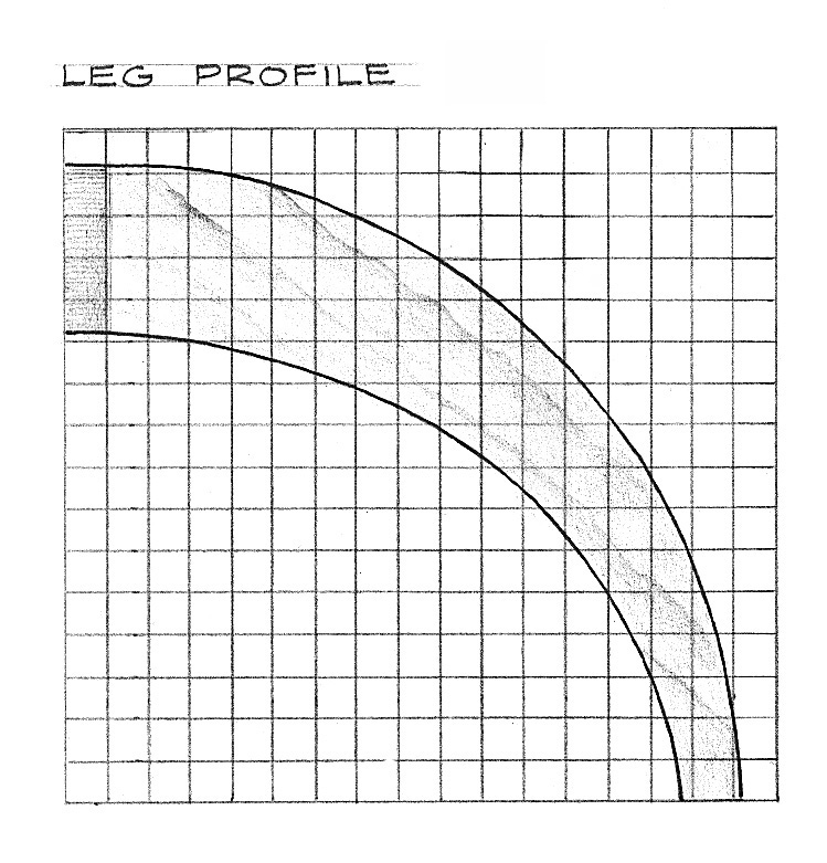
Cut out each leg on your band saw. Then clean up the saw marks with a rasp and sandpaper.

Mark the shoulders of each tenon and then, with a backsaw, cut each shoulder to depth. Then rough in the tenon cheeks.
Use a knife against a straight-edge (I used an old flexible scraper) clamped to the work to mark the shoulders of each tenon. Then with a fine-toothed backsaw, cut each shoulder to depth. With the leg clamped in a vise – end-grain-up – rough in the tenon cheeks with that same backsaw.
Reclamp the leg onto your benchtop and pare the cheeks down to the line.
Bevel the top edges of the mortise with a paring chisel to mate accurately with the leg’s tenon shoulders. Check the fit multiple times. You don’t want to cut too far.

Bevel the top edges of the mortise with a paring chisel to mate accurately with the leg’s tenon shoulders. Check the fit multiple times. You don’t want to cut too far.
Fitting the Tenons
In order for the tenon shoulders – which are cut 90° from the surface of the leg – to mate up tightly with the round pedestal, the top edges of the mortises must be beveled slightly with a paring chisel. Proceed cautiously, testing the leg tenon in the mortise many times as you make your cuts.
Making the Top
You can make a compass for drawing large circles with a length of scrap used as a beam, a nail and a pencil. Close to one end of the scrap, drive a 4d nail so that the point extends through the thickness of the scrap. Bore a pencil-shaft-sized hole through the beam. The center of this hole should be a distance from the nail equal to the radius of the circle you’re about to mark. Insert the pencil into the drilled hole, locking it in place with a set screw driven in one edge of the scrap.
To use the compass, set the nail in a shallow pilot hole that’s drilled into the bottom of your stock. Then rotate the beam around the hole.
Now band saw the circle and clean up the edge with a rasp and sandpaper. Then use your router to cut a small radius on the top and bottom of the tabletop. Finish up with a rasp and sandpaper.
Making the Disk
The tenon at the top of the pedestal fits into a disk that is screwed to the bottom of the tabletop. By orienting the grain in this disk so that it runs perpendicular to the grain in the top, the disk acts to stabilize the thin top, reducing the likelihood of cupping.

Orient the grain in the disk so that it runs perpendicular to the grain in the tabletop. This will allow the disk to resist the top’s natural inclination to cup. When fastening the disk to the bottom of the tabletop, choose a screw length that will allow the screws to penetrate almost completely through the top when the screw head is recessed in the disk.
The curve on the bottom edge of that disk is too large to form with a router; however, you can easily create that profile on your lathe with a fingernail gouge. Begin by fastening the disk to a faceplate with four screws. Then turn the faceplate on your lathe’s drive center.
It’s important that you work the fingernail gouge downhill, that you begin each pass on the edge face of the disk closest to you and work away from the disk’s center point, toward the face of the disk closest to the lathe’s drive center. If you work the other way, you’ll be working uphill, against the grain. This inevitably results in significant tear-out. Working downhill won’t eliminate tear-out, but it will make the tear-out that occurs much less significant.
Fasten the disk to the bottom of the tabletop with four wood screws. Choose a screw length that will allow the screws to penetrate almost completely through the top when the screw head is recessed in the disk. Notice the pitch streaks on the bottom side of my tabletop. This is a common defect in cherry, but it can be placed, as I did here, on hidden surfaces.

Here is the small disk of metal, called a spider, that’s screwed to the bottom of the legs to help hold them together. Use clearance holes in the legs to avoid splitting the tenons.
The ‘Spider’
The Shakers screwed a small disk of metal, called a spider, to the bottoms of the legs on the original to help hold the legs and pedestal together. On the Shaker original, the metal disk had three legs, extending out 1″ or 2″ along the bottoms of each leg. I opted for a simpler form – shown here – which still gives me enough reach along each leg to secure it.
Here are some supplies and tools we find essential in our everyday work around the shop. We may receive a commission from sales referred by our links; however, we have carefully selected these products for their usefulness and quality.