We may receive a commission when you use our affiliate links. However, this does not impact our recommendations.
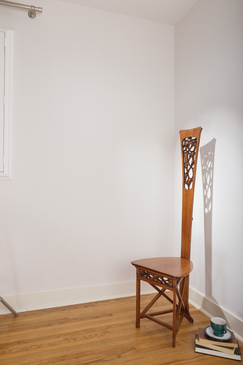
This mahogany Arts & Crafts desk chair exemplifies furniture as art.
Most woodworkers are familiar with Arts & Crafts designers William Morris, Gustav Stickley and Charles and Henry Greene. But Charles Rohlfs’ inspiring work is a bit less well-known.
Rohlfs, trained as a designer and draftsman, spent his early years designing iron stoves and dabbling in theater. After marrying, he and his wife, novelist Anna Katherine Green, established their home in Buffalo, N.Y.
Like many of us who begin woodworking, Rohlfs couldn’t afford to buy quality furniture, so he began to design and build pieces for his home, and later turned it into a profession.
His work displays many common elements of Arts & Crafts furniture, but is set apart by unique design, shapes, artistic ornamentation and carving details. Writers have described Rohlfs’ work as artistic, complex, eclectic and eccentric. His furniture is rare and Rohlfs’ works are highly valued at auction.
Rohlfs’ 1898 desk chair, on which the pierced carvings are said to have been inspired by the cellular structure of oak, is a stunning example of furniture as art. Only four of these are known to exist; one is on display at the Metropolitan Museum of Art in New York. “Antiques Roadshow” estimated in 2006 an original at $80,000 to $100,000.
I’ve been researching and recreating Rohlfs furniture for years, but as a woodworker, it’s a challenge; the few books about Rohlfs have a biographical or art-history focus. I am more interested in how his furniture was made. So with gross dimensions in hand, I developed plans by scaling photographs. After building my first version of the desk chair, I visited the Met to study and photograph a known original. Upon returning home, I updated my plans to better match it.
Select & Prepare Material
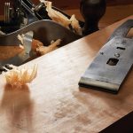
Rohlfs’ works were typically made from oak or ash. He did, however, use mahogany for a number of his pieces, including the desk chair – which is nice, because mahogany is easier to carve than oak.
My first iteration was made from 7⁄8” stock, but it was far too heavy looking. When viewing the original, I could tell it was far more delicate, with wood less than 3⁄4” thick. I made my second version from 5⁄8“-thick stock – but it looked too thin. Since then, I’ve settled on 11⁄16“. To my eye, this thickness looks about right.
If you lay out the parts carefully, the chair can be made from one 3⁄4“-thick board that’s 8″ wide x 10′ long (or about five board feet). If you choose this stock approach, the only glue-up needed is for the seat and foot. The back is just shy of 8″ wide at the top and 3” at the bottom. The offcuts are used to make the legs, side stretchers and cross braces.
Begin with the Seat
This chair breaks down into four major components: seat, back assembly, front assembly and cross-brace assembly.
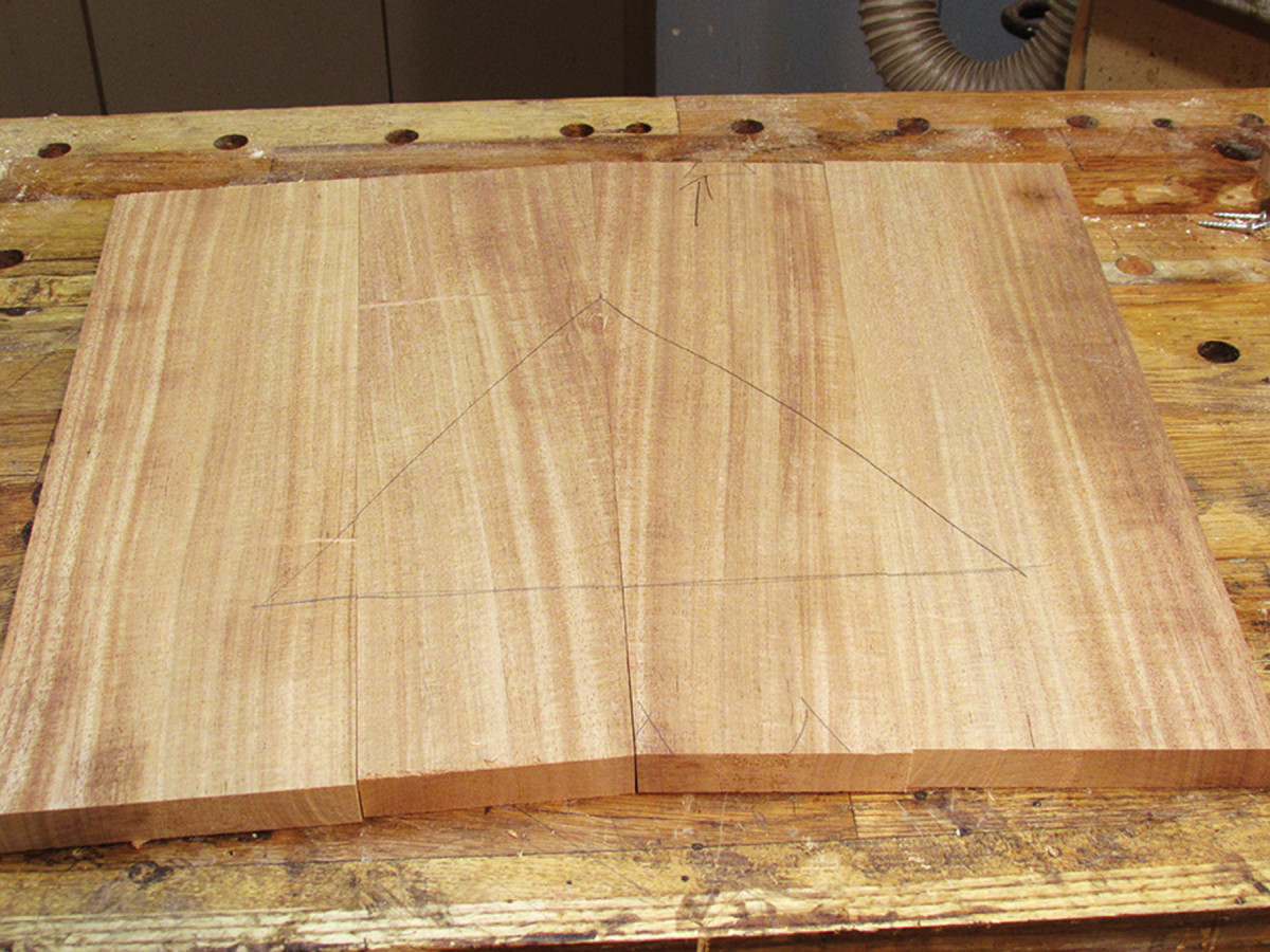
Start by constructing the seat. I had 4″-wide stock on hand, so I made a four-board seat.
I use centerlines (on the seat and back) as reference lines for building the chair. After marking the centerline on the seat, cut the front edge square with this line. Then cut the back edge just a bit larger than final width (I did this at the table saw).
When making a chair, you need to assemble and disassemble it a number of times to size and fit the pieces. I use dowels to aid in assembly and to help consistently locate the parts.
Before going further on the seat, drill a 3⁄8” hole (about 11⁄4” deep) into the back edge at the centerline. This hole will match up with one drilled into the chair back.
Musical influence. I tapered the inner two boards by 1″. This creates a pleasing V pattern that complements the guitar pick shape of the seat.
Next, drill a 3⁄8” blind dowel hole to locate the bottom of the seat with the top rail. This hole, drilled on the underside of the seat along its centerline, is 11⁄2” back from the front edge of the seat.
Now, set your table saw blade at 3° and cut the back of the seat to final width. The 3° angle matches the angle of the chair back.
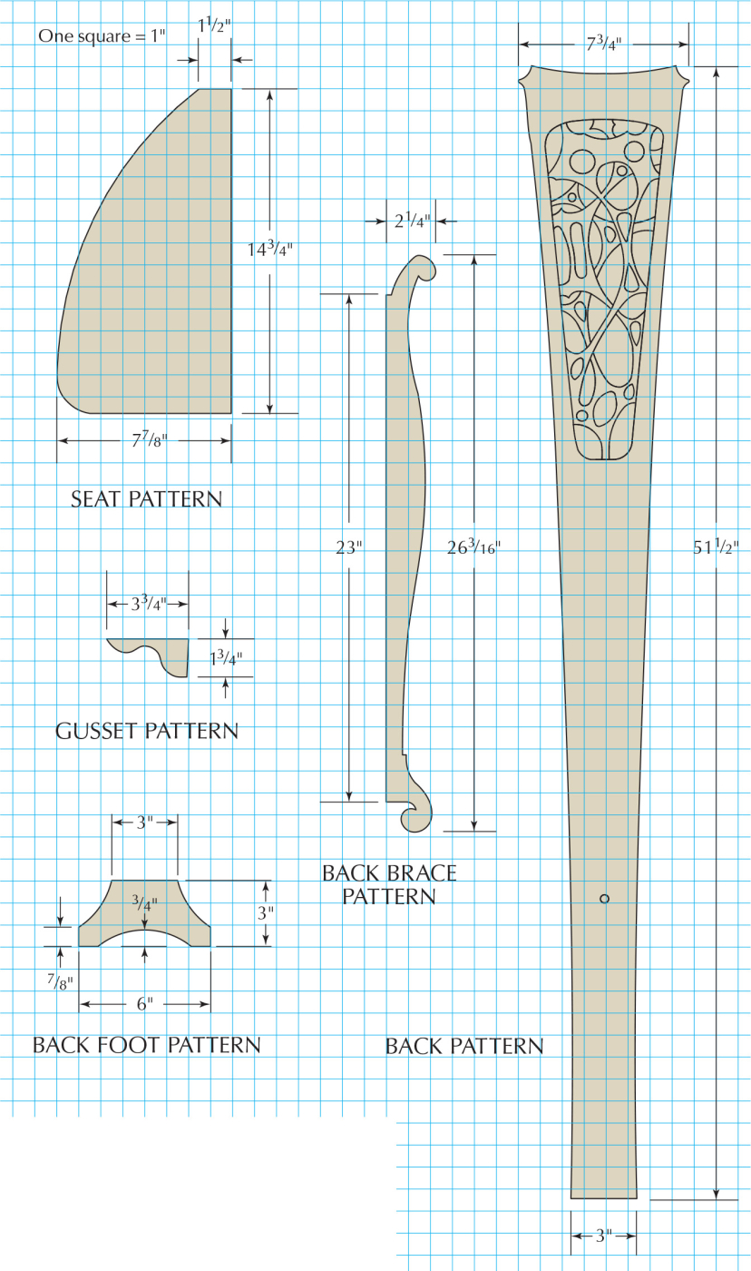
Make a template of one-half of the seat, locate it along the centerline and trace the shape. Flip the template over draw the other half. Cut the seat at the band saw, cutting close but leaving the line. Use a block plane and rasps bring the seat to final shape.
Step down. Use a 3⁄8″, then a 3⁄16″ rabbet bit to make the step profile. Stop the 3⁄8″ rabbet 1″ from the back edge and the 3⁄16″ rabbet 11⁄4″ from the back edge.
To finish up the seat, rout a stepped profile on the edge.
Back
Begin work on the back by making a full-size pattern. I printed a paper template, glued it to a 3⁄4“-thick board and cut out the pattern at the band saw. You’ll use the pattern to rout the final shape of the back, so spend some time smoothing the edges and fairing the curves. So I can always locate the centerline of the back, I cut two small notches into the top and bottom of my template.
Patterns. Although it takes some time to make full-sized patterns and templates, when you make your second chair (and you will) the initial investment pays off.
The back is cut from a board 8″ wide x 52″ long. Mark a vertical centerline on the workpiece. While the edges are still parallel and square, lay out the point where the seat and back connect along the centerline of the seat, 13-7⁄16” up from the bottom edge of the back. With a square, draw a line across the back board. Then drill a 3⁄8” hole at the centerline at a 3° angle to match the slope of the back. This hole will house a 3⁄8” dowel that will mate with the hole drilled into the back edge of the seat (the back brace, when installed, will cover it).
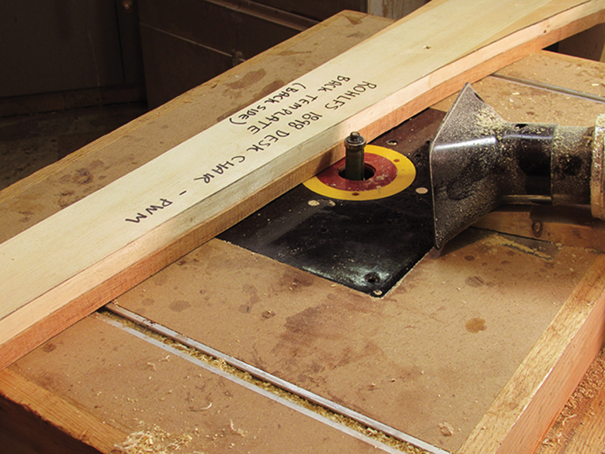
Shapely back. Attach the roughed-out back to the template (being careful to line up the centerlines). Rout the finished shape with a flush-trim bit.
Using the template, trace the shape of the back and cut it at the band saw (leaving the line). Reattach the template and rout the final shape of the back with a flush-trim bit.
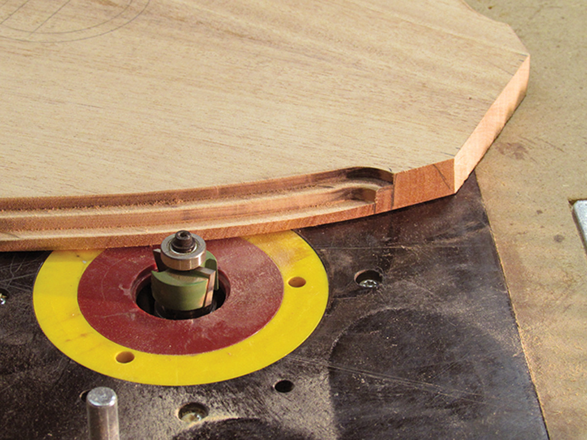
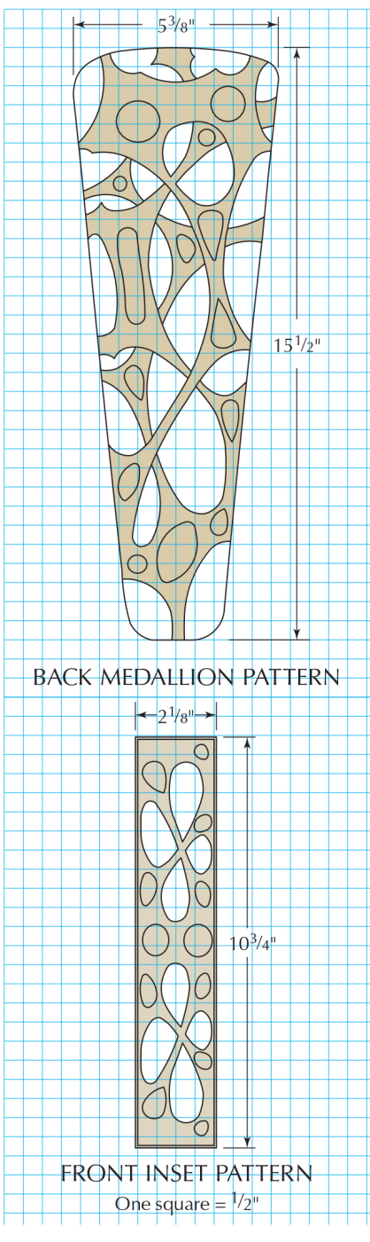
On the edge. With double-sided tape, attach the template to the front side of the back. Use a pattern-routing bit to cut the edges of the medallion to a depth of 3⁄16″.
The carved medallion at the top of the back is recessed 3⁄16” from the front face.
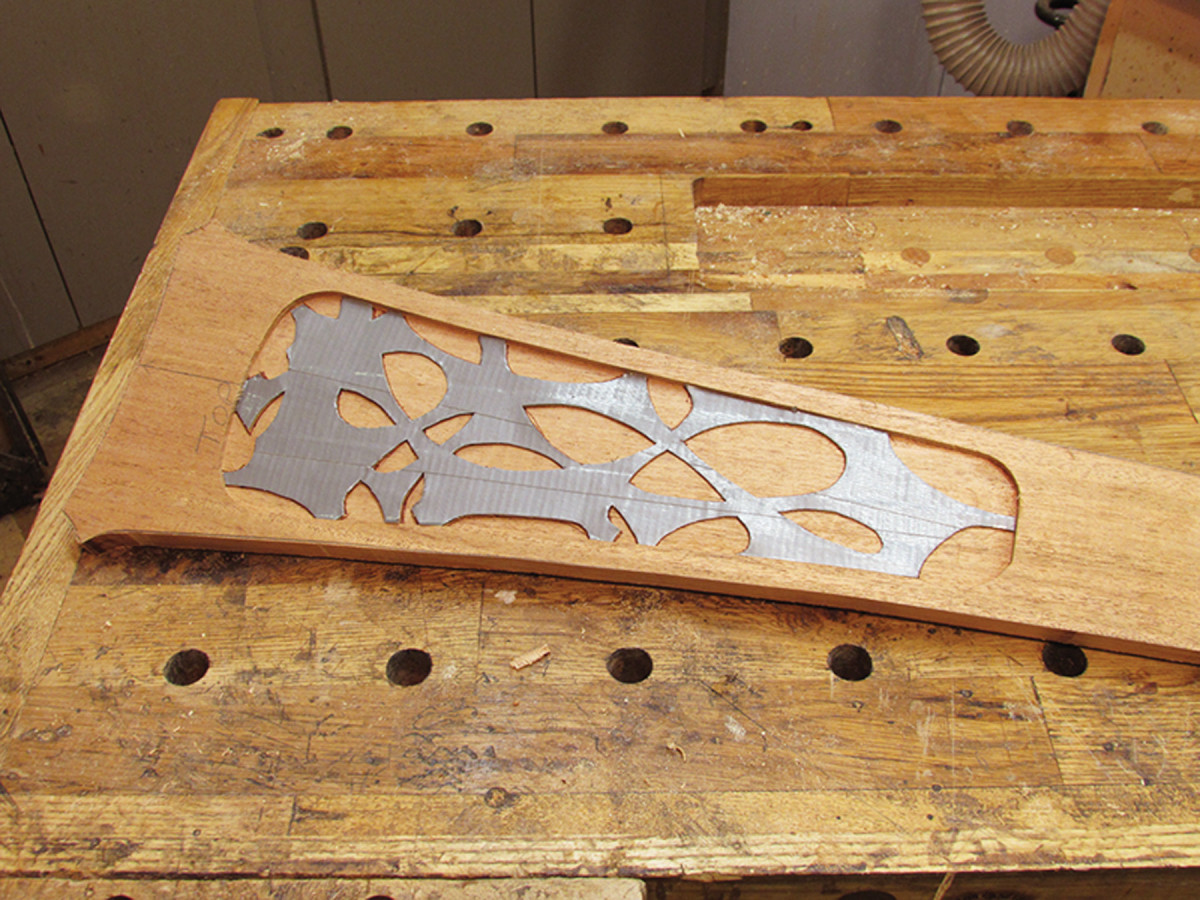
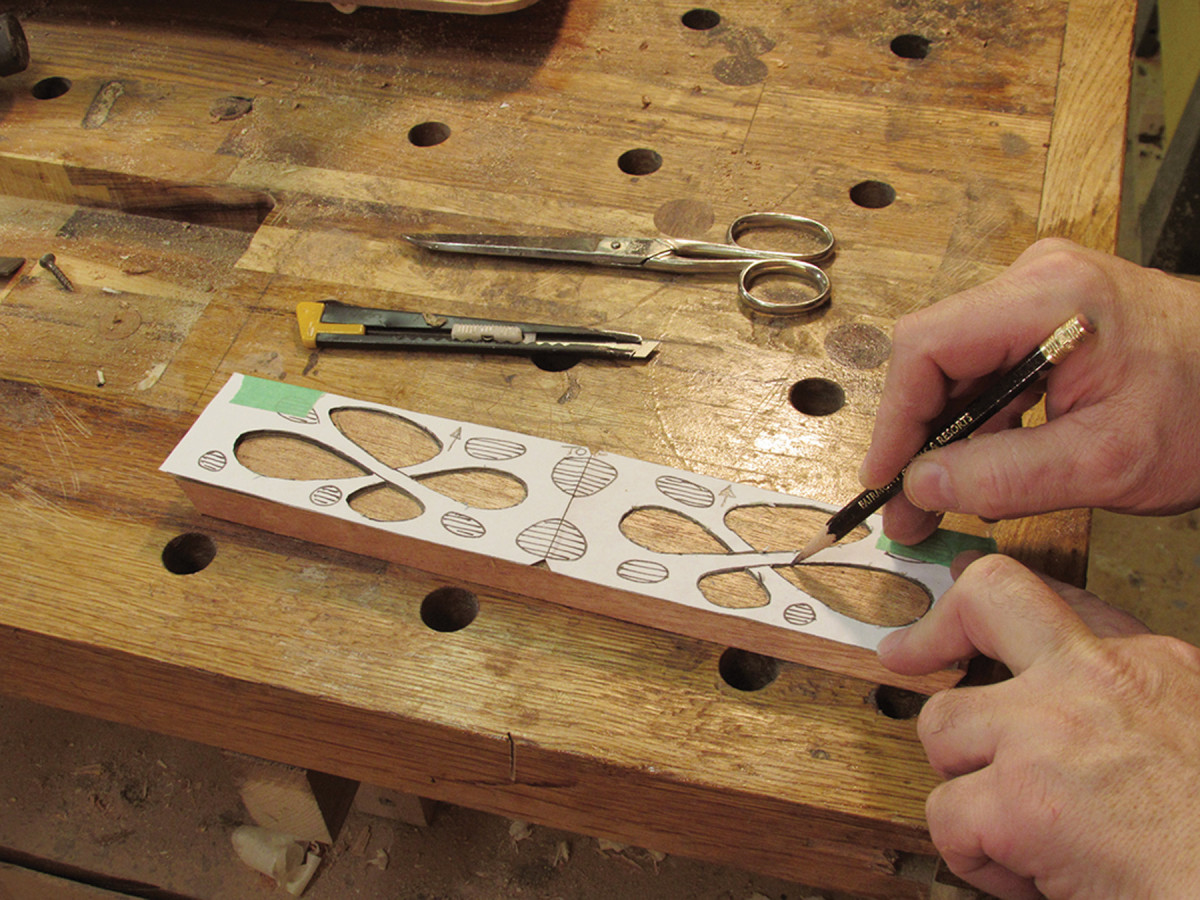
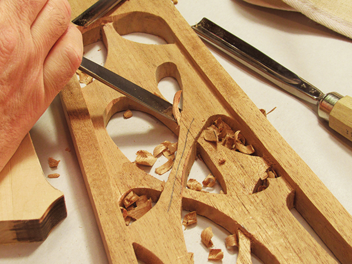
Pattern work. Place the webbing pattern into the medallion and draw the outline. Drill out most of the waste, then use a jigsaw or scroll saw to cut to the lines.
Now place the webbing pattern into the medallion and draw the outline. Drill a number of clearance holes and, using a scroll saw or jigsaw, cut the pattern, then smooth the edges.
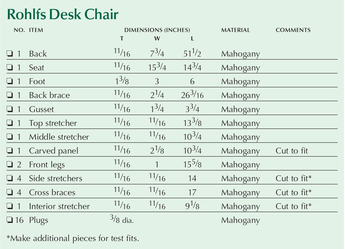
Rohlfs Desk Chair Cut List
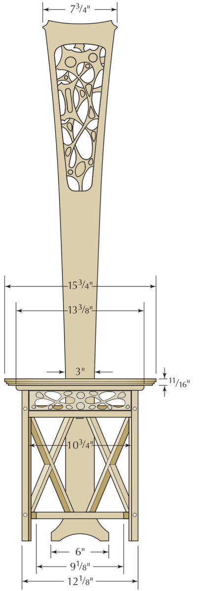
Elevation
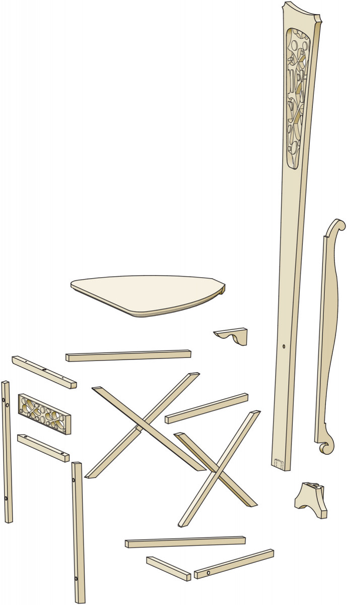
Exploded View
Foot Plan
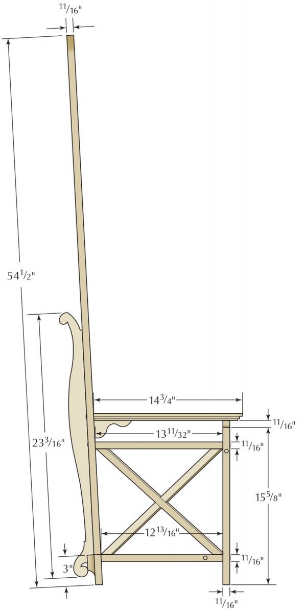
Profile
Foot
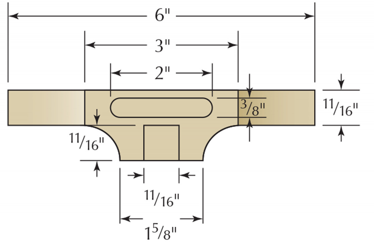
To make the 1-3⁄8“-wide x 3″-wide x 6”-long wishbone-shaped foot, I glued together two pieces of 11⁄16” material.
The foot is attached to the back with a 3⁄8“-thick floating tenon. Cut a 2”-wide x 1-1⁄2“-deep mortise before shaping the foot. I used a plunge router and a shop-made mortising jig, but you can use your preferred method for cutting mortises. Cut a matching mortise into the bottom edge of the back.
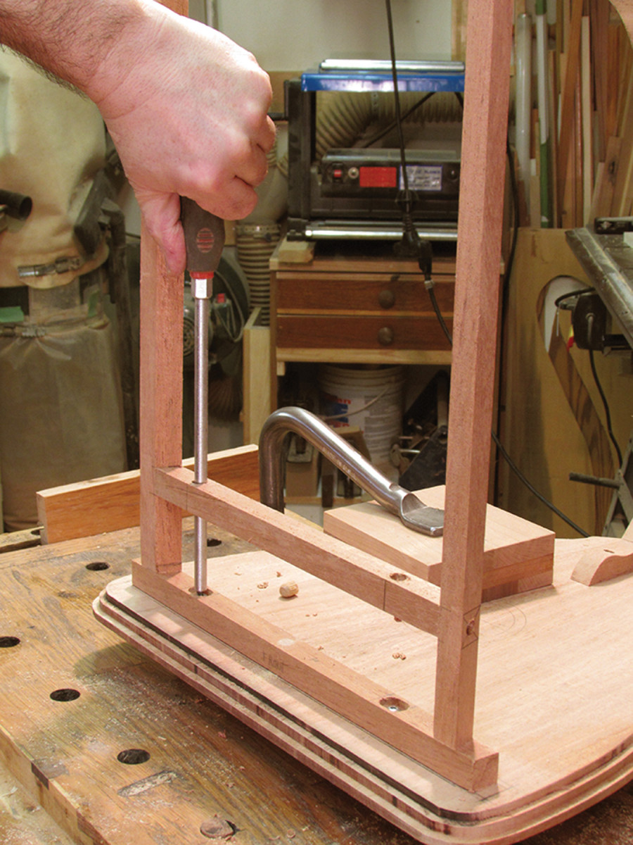
Cover up. Attach the bottom diagonal stretchers with screws driven through the back of the foot. Once the screws are installed, the mortise will be plugged and covered by the back brace.
Cover up. Attach the bottom diagonal stretchers with screws driven through the back of the foot. Once the screws are installed, the mortise will be plugged and covered by the back brace.
Shape the foot at the band saw and fair it with an oscillating spindle sander, then cut an 11⁄16“-deep dado into the back that will house the back brace. I roughed out the dado at the drill press using a Forstner bit and squared it up with a chisel. The final task on the foot is to bevel the bottom at 3°.
Front Assembly
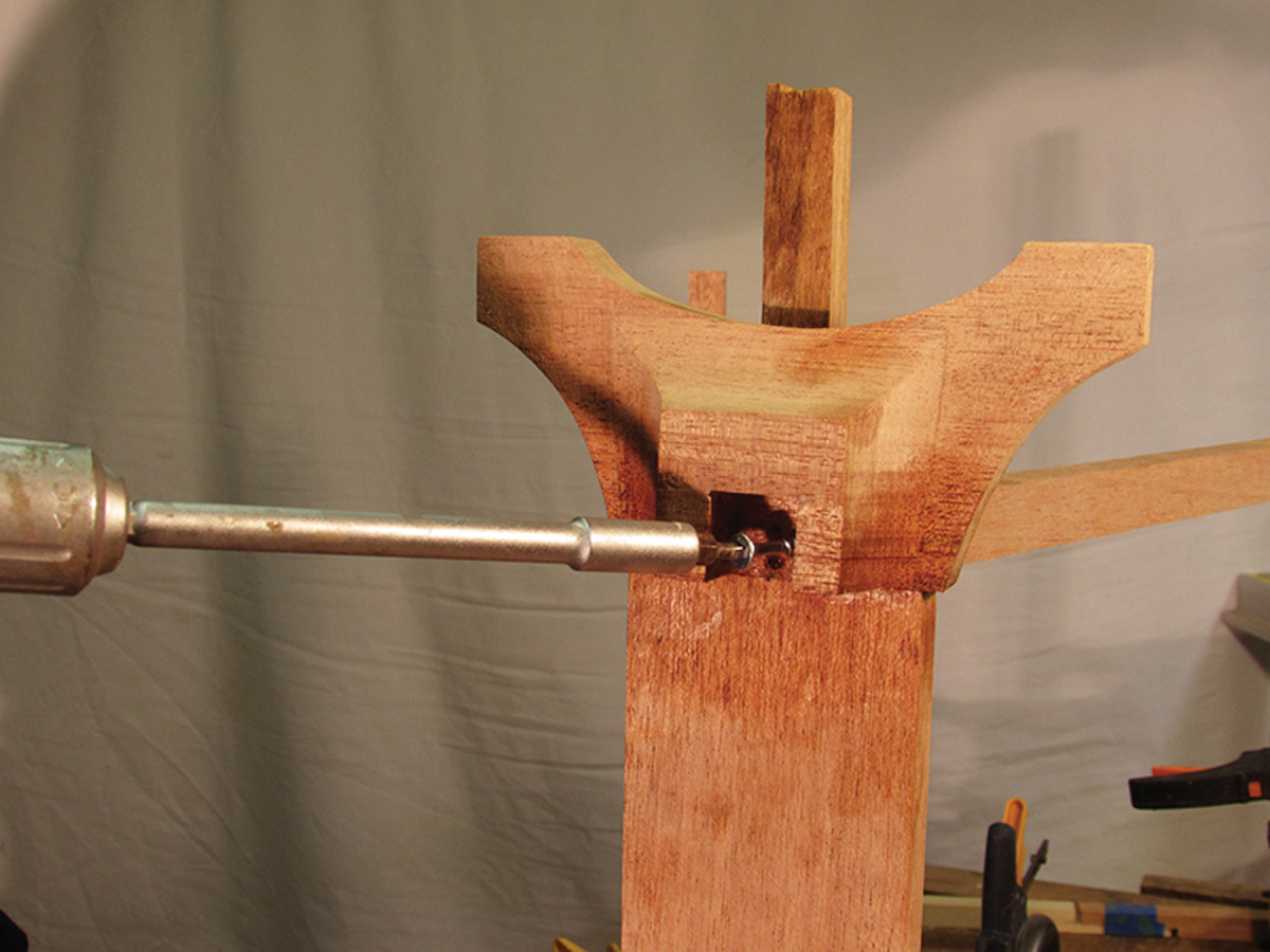
Easy access. Drill two 3⁄8″ holes through the middle stretcher 15⁄8″ from each end. When attaching the leg assembly to the seat, these holes will allow you to insert a screwdriver to access the screws.
The front-leg assembly consists of five pieces: two parallelogram-shaped legs, a top stretcher, a middle stretcher and the carved panel.
The 11⁄16” x 1″ legs are cut at a 21° angle (the 11⁄16” faces are the front and back).
Cut the top stretcher to length and round over the two ends. At the midpoint on the stretcher, drill a 3⁄8” hole. This will house a 3⁄8” dowel that mates with the hole drilled into the seat.
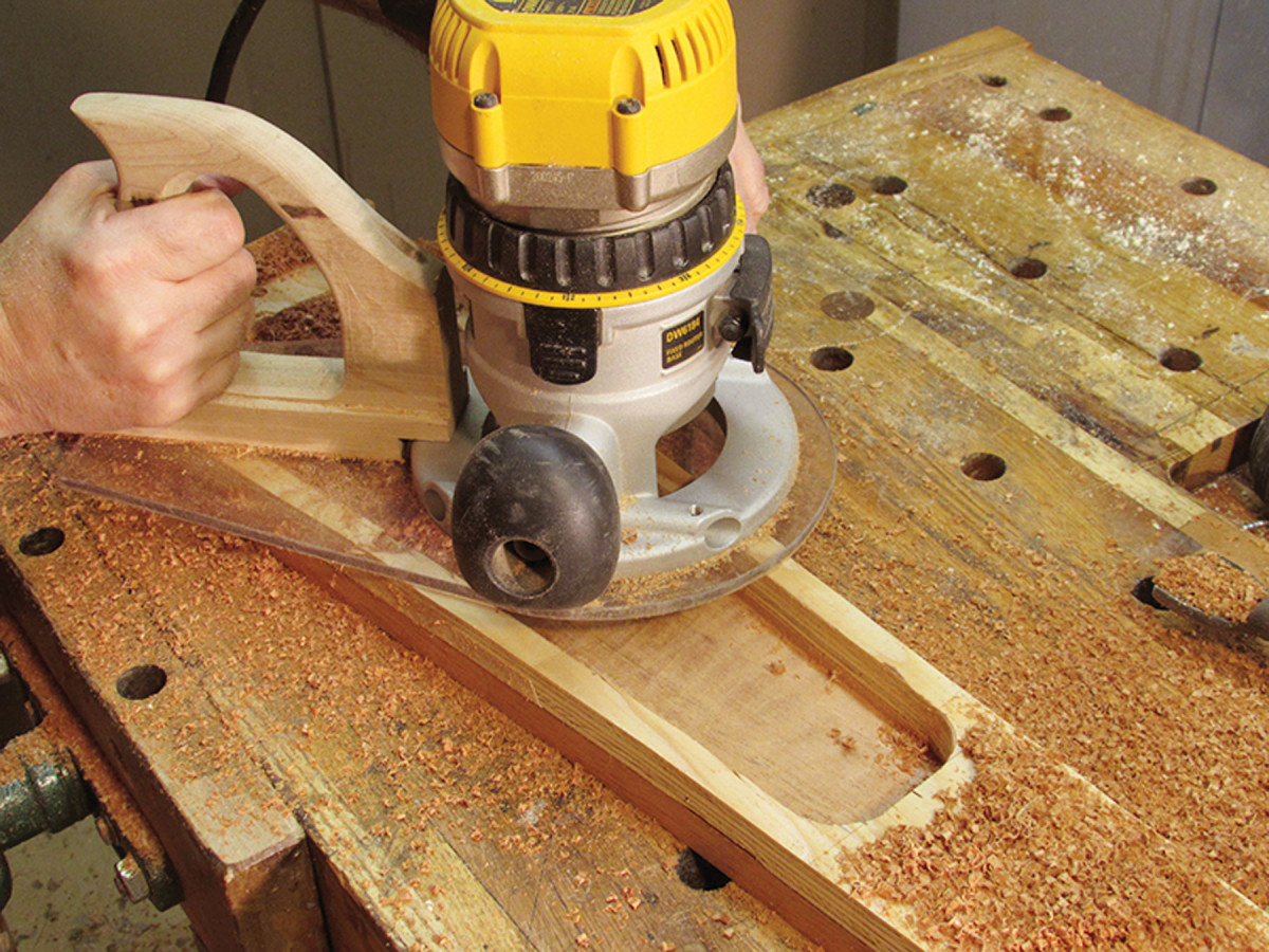
The stretcher is screwed to the underside of the seat. To allow for wood movement, I rout two oval screw slots about 21⁄2” from each end.
The middle stretcher is 103⁄4” long, and each end is cut at a 21° angle. This stretcher is located 21⁄8” below the top of the leg. Mark its location on the front legs and drill pilot holes into the legs and stretchers. (I use spring clamps to hold everything together.)
Back it up. Use the locator dowel to position the back onto the seat. Once the back is positioned correctly, drill pilot holes through the back and into the seat. Secure the back with screws.
The carved panel fits into the space created by the top and middle stretcher and front legs. It is glued in place after the front assembly is attached to the seat.
Cut each end of the panel at 21°, and make the panel blank slightly shorter than the middle stretcher to allow for recessing it slightly from the face of the front assembly. As you did on the back, trace the pattern on the front panel, drill clearance holes and cut out the pattern.
To keep everything square and parallel, attach a temporary spacer between the bottom of the legs so the width at the bottom of the legs matches the width where the legs attach to the stretchers. Center the legs along the top rail, clamp them in place and drill pilot holes through the top rail into the legs. Attach the legs to the top stretcher with screws.
Drill countersunk holes to accommodate 3⁄8” plugs, then glue and screw the front-leg assembly together, making sure everything remains square and parallel. After the glue sets, use a block plane to flush the surfaces as needed.
Get Attached
Now you are ready to attach the back and the front-leg assembly to the seat.
The centerline of the back needs to be perpendicular to the face of the seat, otherwise the chair will look like the Leaning Tower of Pisa. I use a fixture clamped to the seat to help line up the back.
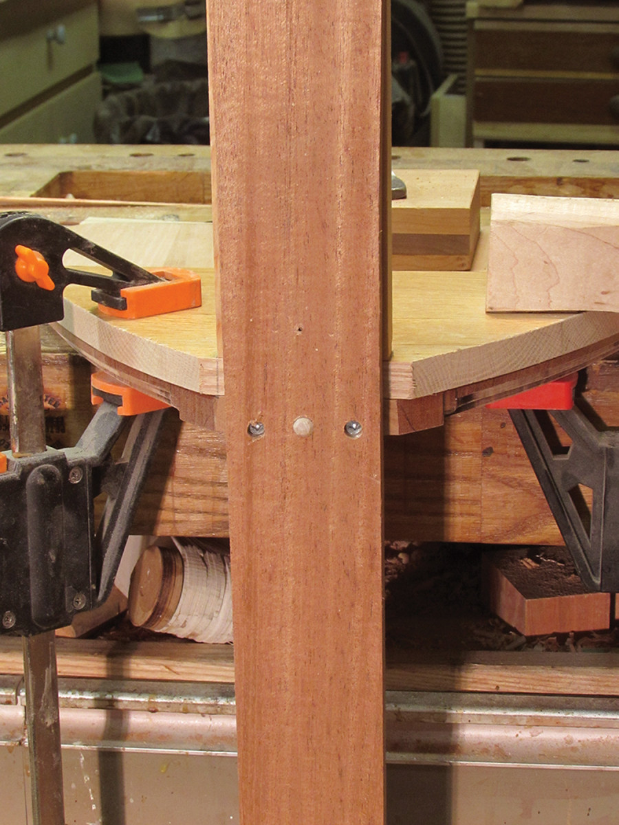
To strengthen the chair, install a gusset between the back and the bottom of the seat. It is screwed into the seat bottom and through the back.
Use a dowel to locate and position the front assembly to the seat. Attach it with two screws, making sure that it is parallel with the seat’s front edge.
With the back and front assembly in position, fit-up the side stretchers and cross braces.
Stretchers & Cross Braces
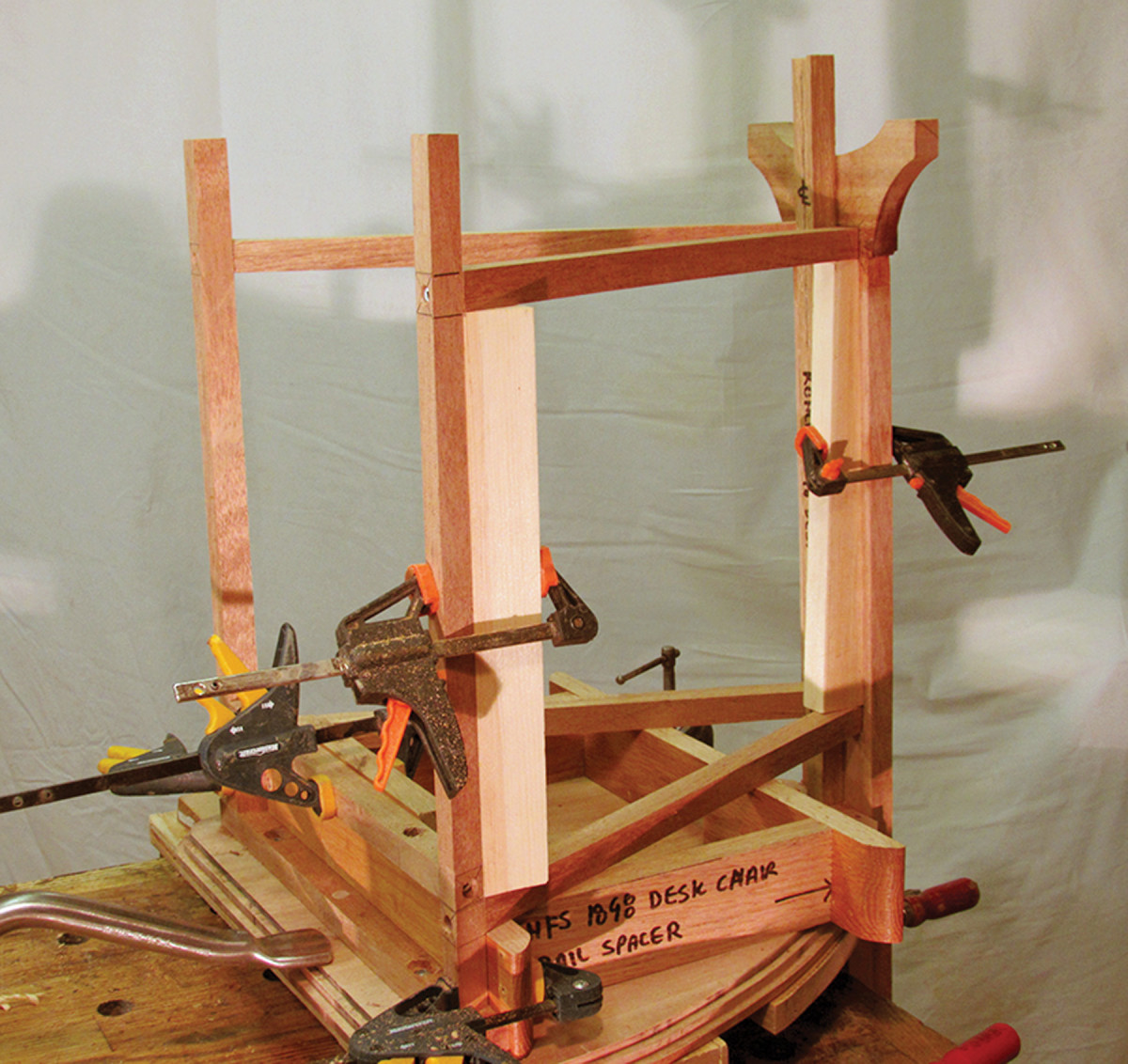
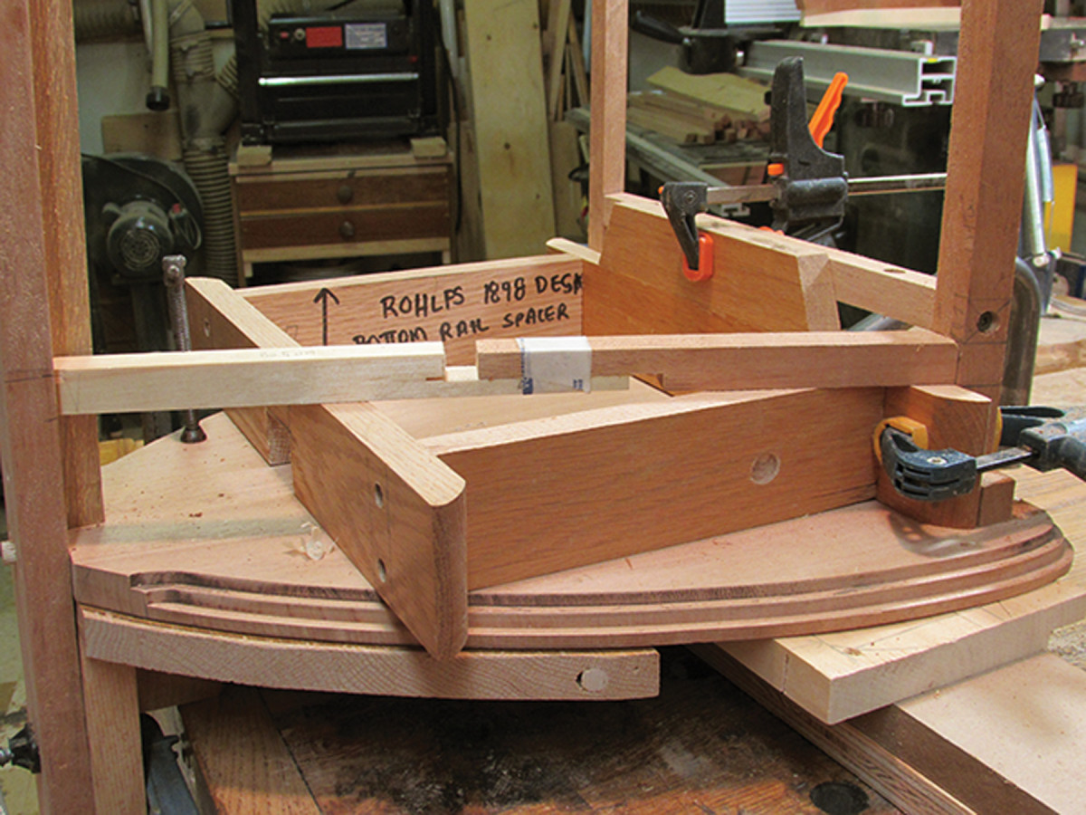
Assembly aids. Various fixtures and spacers hold the chair in alignment and help to locate parts during assembly.
The side stretcher and cross-base assembly adds tremendous strength and rigidity to the chair. To begin work on it, position the chair upside down on your workbench.
Given the slenderness of the parts, it is easy to pull the chair out of alignment. The parts should fit snug but not too tight (or too loose); you don’t want to distort the front assembly or change the angle of the back when it’s screwed in place.
To keep the back aligned vertically and at 3° to the seat, make a fixture that clamps to the seat and back. I also clamp a 5⁄8” spacer along the inside of the back to set the distance between the side stretchers.
A 21⁄8” spacer locates the top side stretchers the correct distance from the seat bottom, and holds them in place as you work. The same spacer is also used to keep the front leg assembly square with the bottom of the seat. Similarly, use spacers to locate and hold the bottom side stretchers in place.
On the stick. The easiest way to measure the stretchers is to use an adjustable story stick.
It is best to make test pieces to fit the side stretchers and cross braces. The various angles can get confusing – it’s hard to get accurate measurements with a tape measure and it is easy to make a mistake.
The front of each side stretcher is cut at 21°. The back edge is a compound angle, cut at 21° and 3°. To make this cut, I set my miter saw at 21° and place the side stretcher on a 3° sled to create the compound angle.
With the stretcher cut to length and fitting snugly, drill a pilot hole though the front leg and into the stretcher.
Mark the outline of the stretcher onto the back. Drill a pilot hole through the back, keeping your drill at the same angle as the stretcher. The pilot hole should come through the back about 1⁄2” from the centerline.
Spacers locate and hold the top of the lower side stretcher flush with the top of the foot. Because the back slopes, the lower side stretchers will be shorter than the top stretchers.
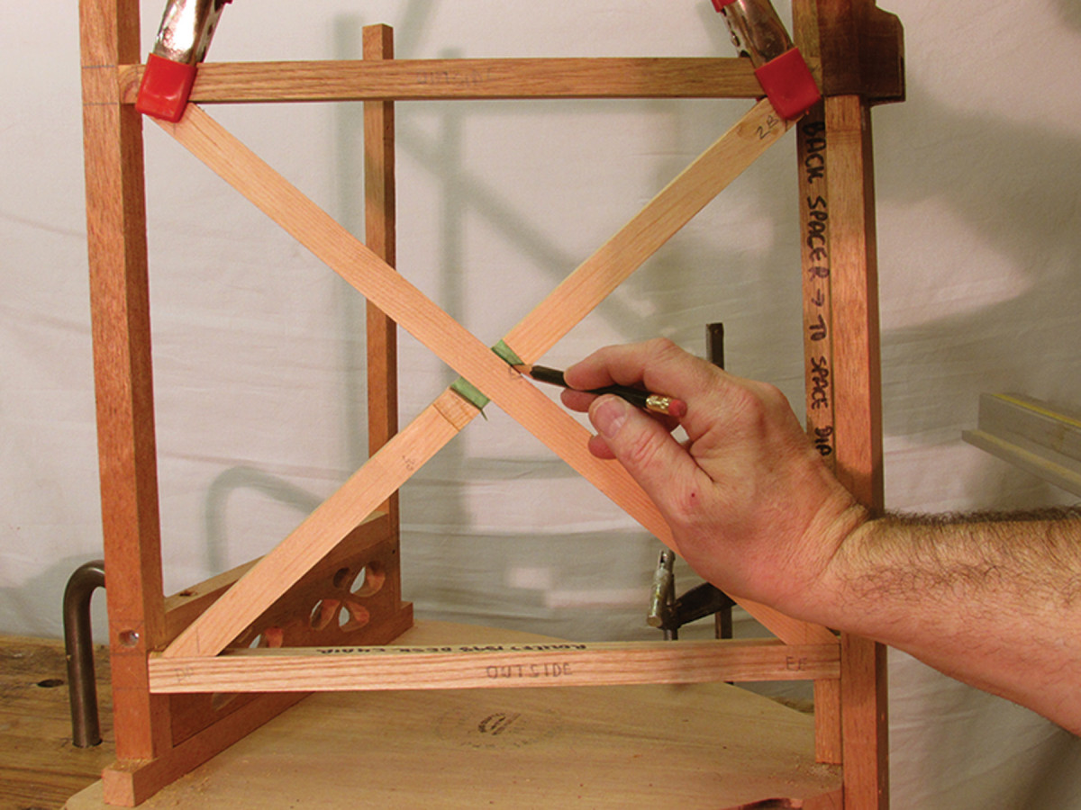
For position only. Using trial pieces with a loosely cut half-lap joint, mark the joint location. Transfer the layout to your final pieces.
With the side stretchers in place, fit up the cross braces, which have a 42° angle at each end.
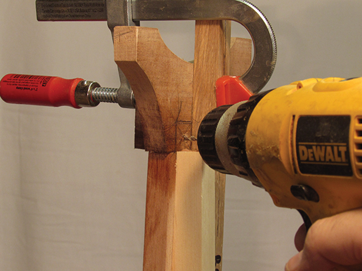
Drill. Mark the location of the stretchers onto the foot and drill pilot holes through the back of the foot and brace dado; this will help you locate screws to attach the side stretchers.
A half-lap joint connects them. Sneak up on the cut, testing the fit and position as you go.
The cross brace is glued at the half-lap joint and to the side stretchers. Use spring clamps hold everything in place.
Stopped hole. The cross braces are securely attached to the side stretchers using 3⁄8″ dowels. Take care not to drill all the way through the show face of the cross-brace pieces.
Once the glue sets, remove the assembly and use dowels to securely attach the cross braces to the stretchers.
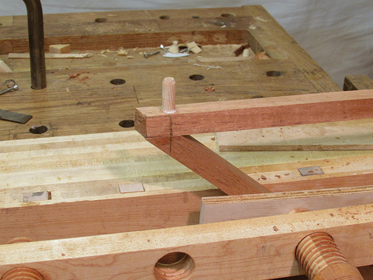
An interior stretcher, set 2-3⁄8” back from the front of the legs, connects the two lower side stretchers. Mark its length, cut each end at 21° and secure it with screws drilled through the side stretchers.
Back Brace
The back brace is installed last, and fits into the dado on the back of the foot. It stiffens the back and conceals a number of the screw holes used to assemble the chair (see Back Brace Pattern with cutlist and other diagrams). Attach the brace to the back with four screws along the centerline, then plug the holes with faceted plugs.
Plugs & Screws
Rohlfs used faceted wooden plugs to conceal the screws. A carving knife makes quick work of shaping the three facets on each 3⁄8” plug to match the originals.
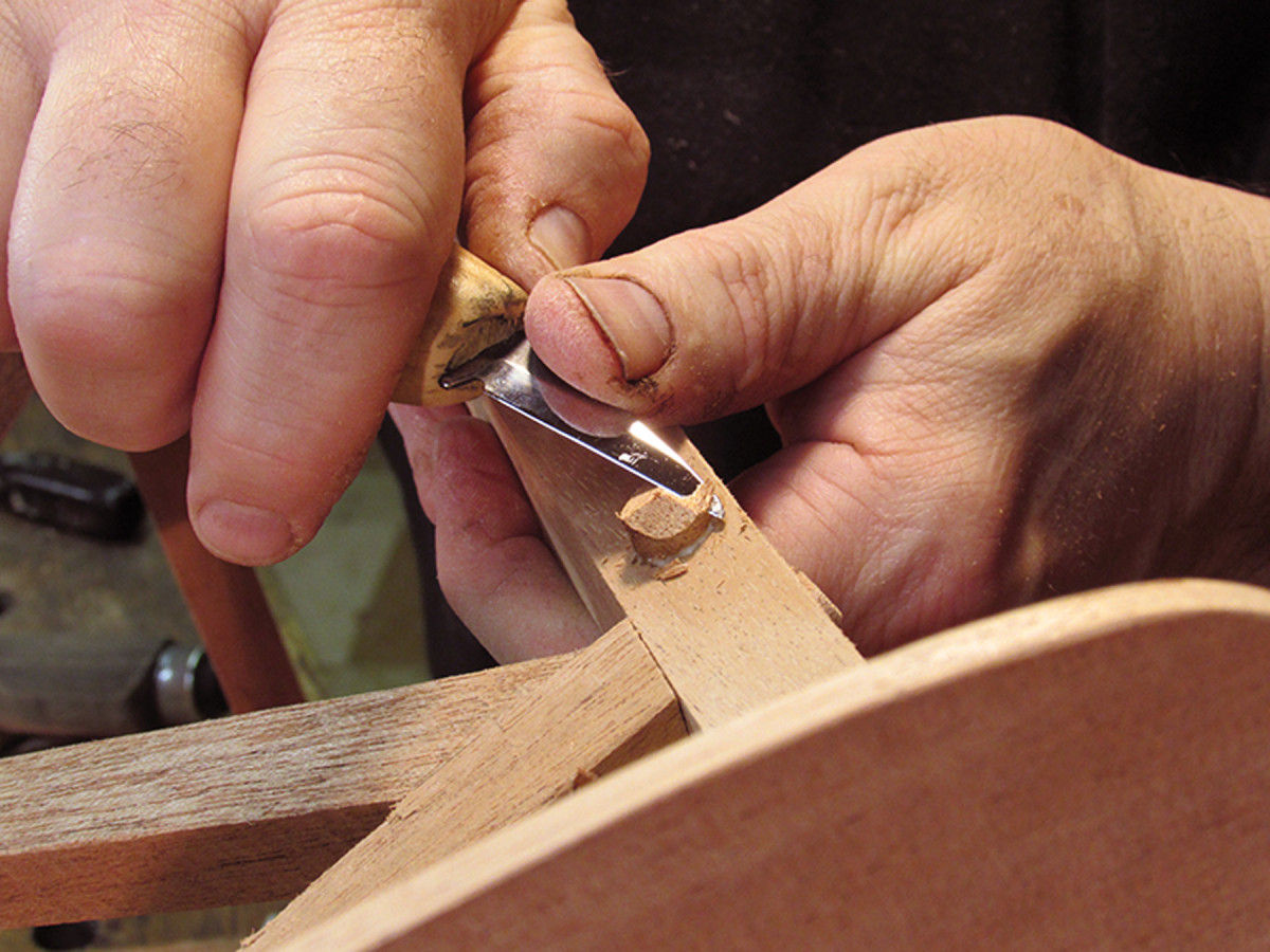
Faceted plugs. Shape the face of the wooden plugs with a carving knife.
Most of the screws are driven into end grain, which is not the optimal situation for a screw joint. To increase the holding power, I inserted 3⁄8” dowel plugs along the path of each screw to provide some long grain for the screw to bite into. I used #8 screws during the initial assembly, and once the chair was assembled, I replaced each #8 screw with a 2″-long #10 screw. This is a pretty beefy screw in fairly slender stock. Take care to drill appropriate pilot holes and don’t overtighten – otherwise, you risk splitting the wood.
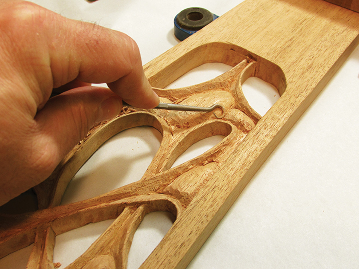
Carving Details
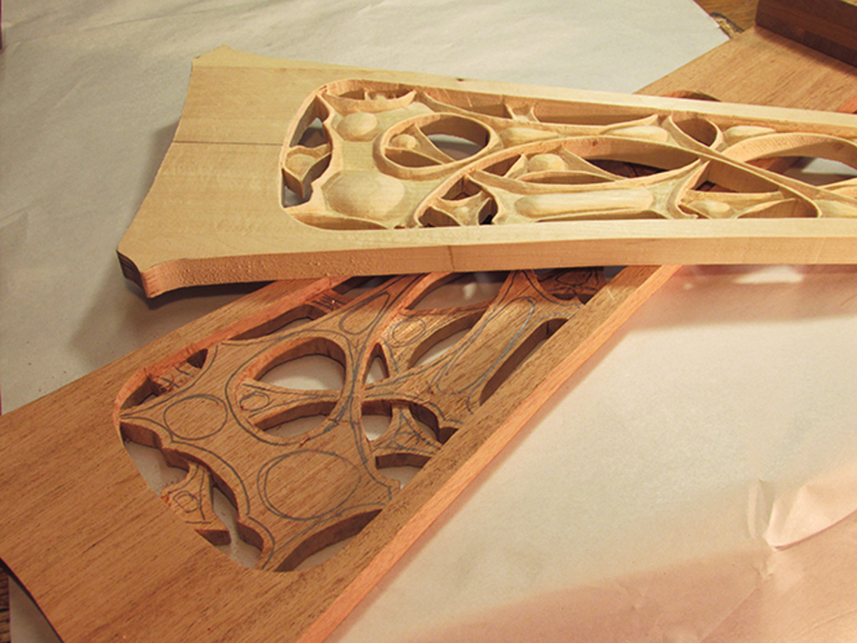
Practice. To warm up and flex my carving muscles, I first carved the patterns in basswood.
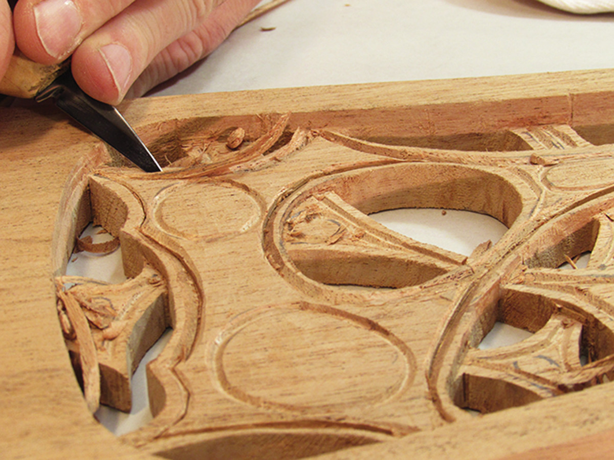
Passover. Make stop cuts to define areas where one strand passes under the other. Then lower that portion to the stop cut.
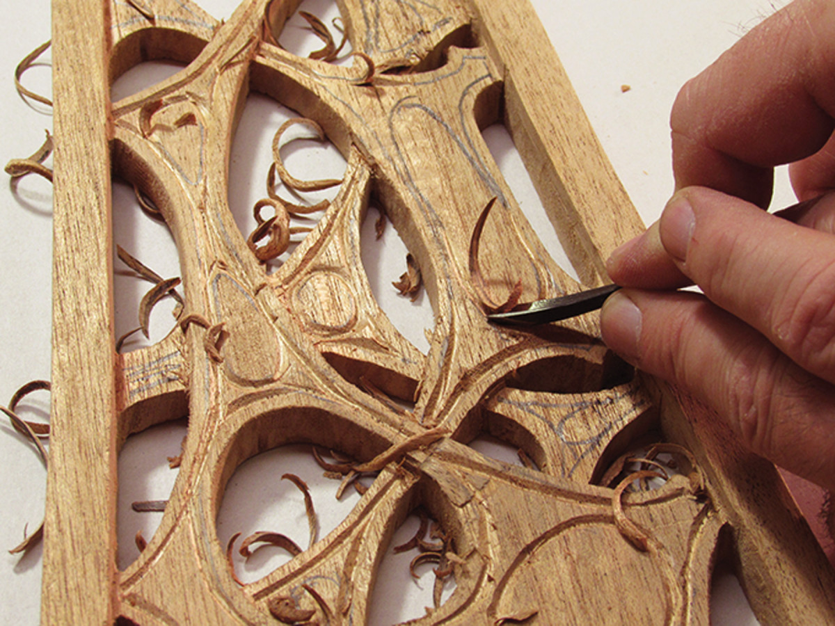
Shallow V. Use a small V-gouge to cut along your layout lines. When cutting along the thinner strands, watch the grain direction so as not to tear out.
Definition. Next, define and deepen the webbing using a detail knife. Make a stop cut along the center of the V-groove, then pare away along each side of the webbing to deepen it. (In more difficult areas, you might find it easier pare with a small straight or skew gouge.)
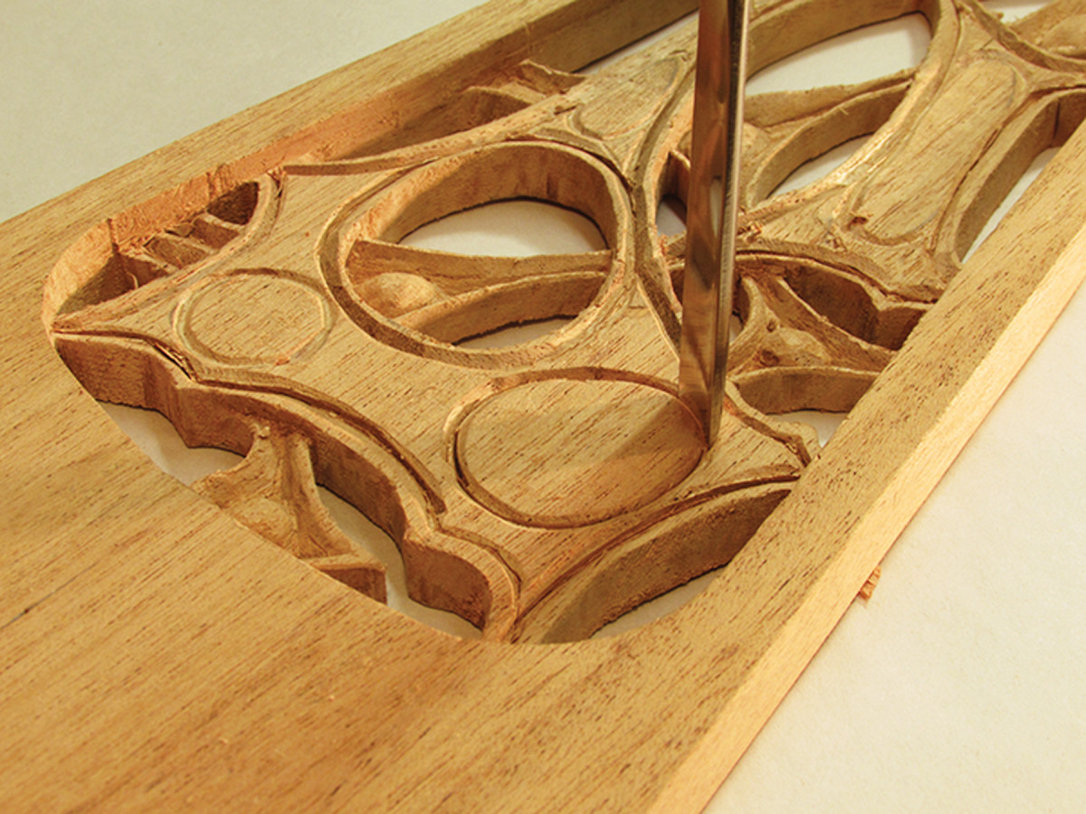
Nodes. Now it’s time to deepen and define each node. Use a gouge with a matching curve to define each by making stops cuts into the V- groove around each of them.
Pare down. Lower the background by paring away the wood to these stop-cuts.
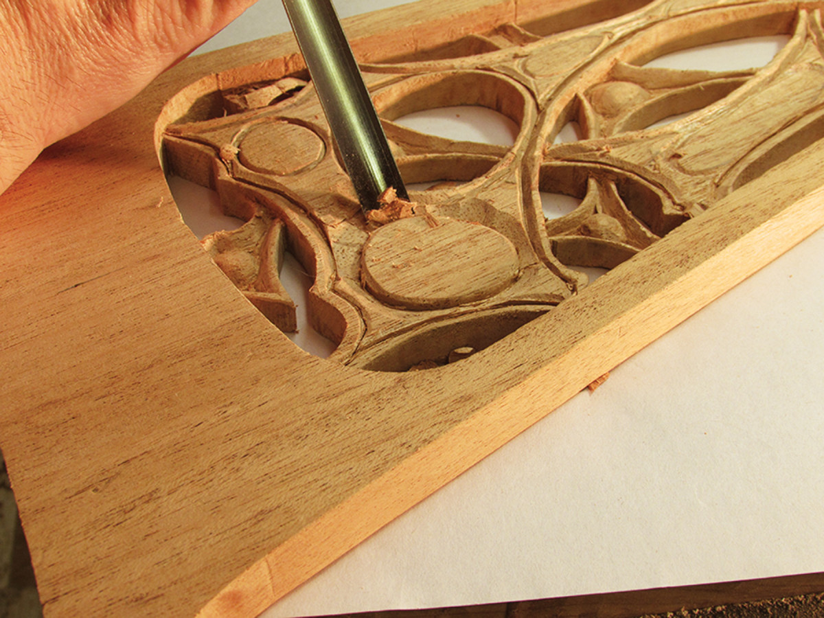
Add curves. Use a straight gouge to shape the curved surface of the each node. Be careful – the edge of the webbing is fragile and prone to chip.
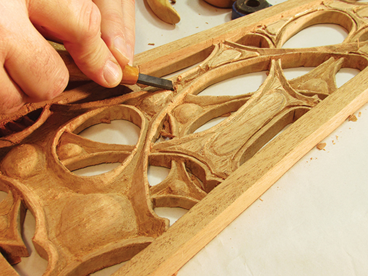
Smooth. To strengthen and support the edge, slightly bevel the other side of the webbing. Use detail rifflers to remove any tool marks and smooth the surface.
Carving Inset
The carving process is the same for the front panel and the back. Begin by laying out the pattern defining the overlapping strands, the webbing and the perimeter of each node.
I started by carving a basswood prototype of the front panel and back medallion.
Finish
I darkened the wood a bit with some English chestnut stain, leaving more finish in the carved portions, then applied several coats of a tung oil finish.
Like a favorite picture, painting or sculpture, the 1898 desk chair needs to be prominently displayed. But get ready to make another one because the first visitor to your home will want one.
“It does not follow that large means are important toward satisfying the taste for things fit or beautiful.”
—Charles Rohlfs (1853-1936), from The Rotarian, Vol. VI, No.1, 1915
Free Plan: Download a free SketchUp model of this project.
Here are some supplies and tools we find essential in our everyday work around the shop. We may receive a commission from sales referred by our links; however, we have carefully selected these products for their usefulness and quality.