We may receive a commission when you use our affiliate links. However, this does not impact our recommendations.

These jigs help you hand cut flawless mortise-and-tenon joints.
By Jeff Miller
Mortise-and-tenon joints tend to frustrate woodworkers far more than dovetails do. That’s no mystery; they are genuinely harder to cut than dovetails. The large flat tenon cheeks and mortise walls need to be flat, smooth and parallel, the shoulders have to line up perfectly all the way around the tenon, and to get a fit that works, the tolerances are within a couple of thousandths of an inch.
About a year ago, I started fooling around with an idea to make hand-cut mortise-and-tenon joints a little easier. I came up with a pair of simple jigs that make it possible to cut – in conjunction with a good tenon saw and some mortise and paring chisels – accurate, repeatable joints by hand that rival those cut by machine. The jigs cut down on layout as well. And they make it easy to cut angled tenons. The final bonus is that the tenoning jig can actually help improve your saw technique.
That all may sound a bit like I’m peddling snake oil, but the jigs are very simple in concept. There’s a jig for paring mortise walls, and for paring tenons, a sort of an upright miter box combined with a system of spacers. There’s no magic involved. There is, however, a fair bit of tweaking the jigs to tight tolerances.
Is it cheating? Maybe. But cheating in the same way that a shooting board is cheating: easy, accurate results on something you could conceivably do strictly by hand. And you still need good saw and good chisel technique to get the best results.
Also, the jigs can certainly be used independently. But they work better as a complete system.
The Mortise-paring Jig
Chopping mortises with a mortise chisel is surprisingly fast and reasonably accurate, but for the best results, it helps to pare the side walls to clean them up. One of the easiest ways to do that and get straight, square results is to clamp a guide block to your workpiece to act as a reference for your chisel. This jig is actually a combination of chisel guides. With it, you can pare both sides of a specific-size mortise located a pre-determined distance from the edge of the workpiece. The jig references off only one edge of the workpiece for greater accuracy. And you don’t need to chop by hand for the jig to work; it will clean up the sides of a mortise no matter how you cut it.
This might seem like a lot of work for a specific size joint, but the jig is very quick to make, and most of the time, you need to cut multiples of the same joint for your projects. Make up one for a table or chair, and it might well do for most other tables or chairs you build.
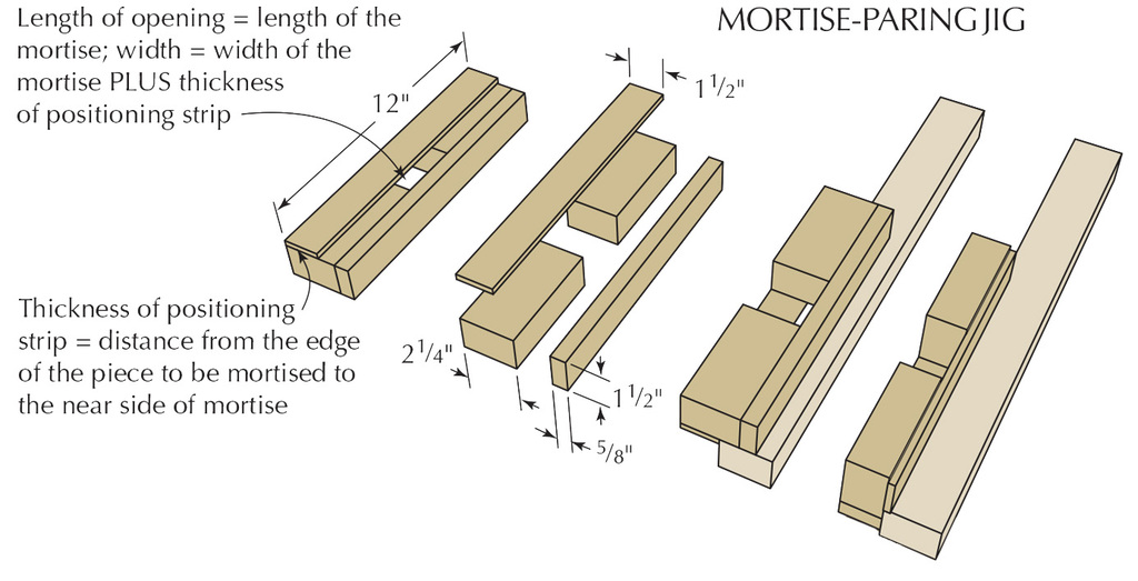
Once you’ve decided on the mortise location and size, you’re ready to make the jig. The blank should be 1 1⁄2″ thick and 12″ long, although it’s helpful to have some extra length. Start by add- ing the distance from the mortise to the edge of the workpiece to 31⁄8″ (this assumes an 1⁄8″ table saw blade; or you can calculate 2 7⁄8″ plus the width of two kerfs) to come up with the width of the jig blank.
Rip the blank into three strips: one equal in width to the distance from the mortise to the edge, one 5⁄8″ wide and the other 2 1⁄4″ wide. The 2 1⁄4″ block should then be crosscut to two equal lengths. The pieces will be spaced equal to the length of the mortise (or longer, if you want to use the jig for various lengths of mortises). The simplest way to do this is to cut the block in half, then separate the two halves the desired amount. (You can trim off the ends later, and maybe even use the trimmed parts for another jig.) Clamp and screw the 5⁄8″ strip to the separated 2 1⁄4″ blocks. Plane flush if necessary.
The placement of the remaining positioning strip will determine the exact size of the mortise. This strip lays flat on the 2 1⁄4″-wide block faces, and the opening between the edge of this and the 5⁄8″ strip should equal the width of the mortise plus the distance from the mortise to the edge of the workpiece. An easy way to come up with this dimension without measuring or fussing around is to take an offcut of the positioning strip and a similarly sized piece of scrap that is the same thickness as the tenon you want. Use the two pieces as spacers to align and space the positioning strip. Clamp everything carefully in place, then screw the strip to the 2 1⁄4″ blocks.
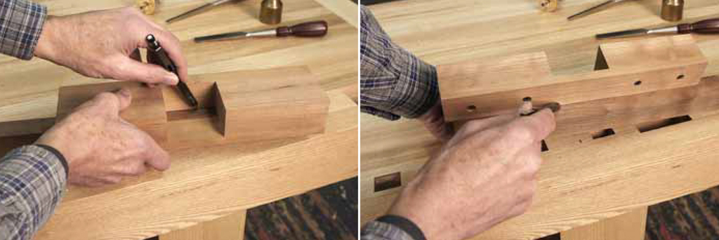
Mortise layout. Hold the positioning strip against your reference edge and scribe the far side and two ends of your mortise. Then flip the jig around and scribe the near side.
Using the Jig
You can easily use this jig for the initial layout of the mortise. Hold the jig in place against your workpiece with the positioning strip against the reference edge, and scribe the far side and the two ends of the mortise. Then flip the jig around so the positioning strip is oriented vertically, and use the rest of the jig as a fence against the workpiece. Scribe the near side of the mortise along the positioning strip.
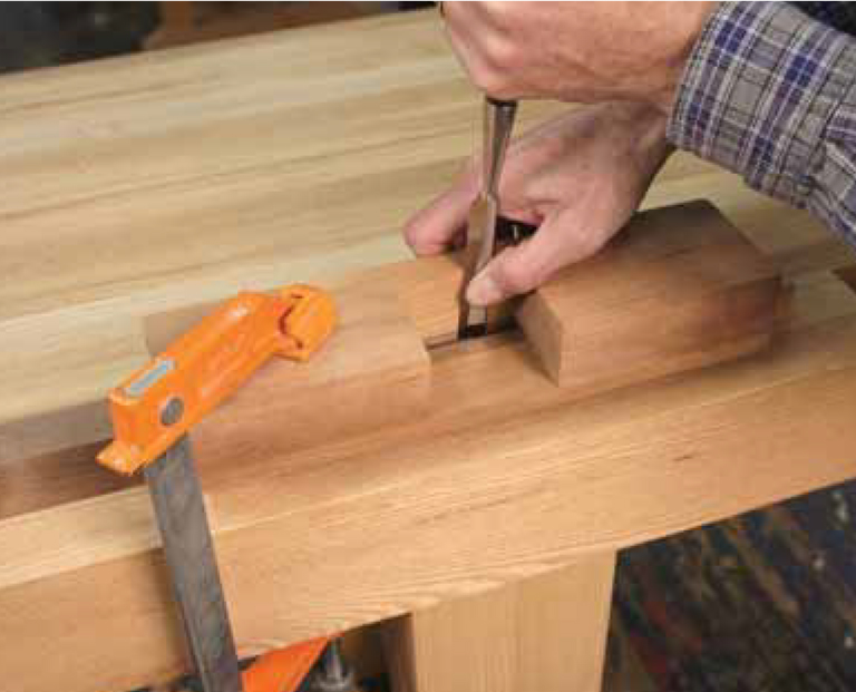
Crisp mortises. With this jig, you can pare all your mortise walls clean – hand cut or not.
I usually chop a slightly narrower mortise inside these scribed lines, although you can also excavate it using other methods. Once the mortise has been roughed out, clamp the jig back into position with the positioning strip against the reference edge and hold a 1⁄2″- or 5⁄8″-wide paring chisel with its back against the inside face of the jig. Pare down while still holding the back of the chisel tight to the jig face. Then move the chisel along just a bit and make overlapping paring cuts until you’ve cleaned up the whole side of the mortise. Don’t try to take off too much wood as you pare; the more you take off, the harder you’ll work, and the less likely you are to be accurate. Instead, you may want to take a preliminary pass or two to get closer to the final line (and the jig).
I keep a dedicated chisel for this type of paring, which I ground to a 20° bevel and a 23° micro-bevel. It makes the paring easier, and seems to leave a cleaner side wall to the mortise. But the edge is fragile, and I never use this chisel for anything other than this work.
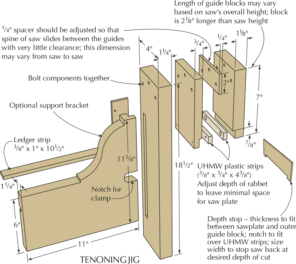
The Tenoning Jig
The core of the tenoning jig is the saw guide – a slot for the spine of the tenon saw constructed out of two saw guide blocks separated by a spacer (all made of wood), and a pair of ultra-high molecular weight (UHMW) plastic guides for the sawplate. The combination creates a guide that makes it hard to cut other than dead straight and square. The rest of the jig provides support for the workpiece and a way to clamp the jig firmly to a workbench.
The critical dimensions of the saw guide are based specifically on your tenoning saw. Measure carefully the thickness of the saw’s back and also the saw’s overall height (the back plus the blade). The back measurement, with a little added clearance, provides the thickness for the jig’s spacer. The overall height of the saw plus 2 1⁄8″ will be the overall length of the inner and outer saw guide blocks.
Although the spacer is small, the overall accuracy of the jig depends on its precision. Because it is both difficult and dangerous to try to work such a small piece, mill up a larger strip that’s at least 12″ long and then cut it down to size. The two sides of the spacer should be carefully milled so that they are perfectly parallel and roughly the thickness of the saw back (but no thicker).
Eventually, you want to wind up with a spacer that is two to three thousandths of an inch thicker than the saw’s back. This will provide just the right amount of clearance. But don’t bother measuring this. You’re better off just testing the spacer and adding shims to adjust to a sliding fit that’s free of slop.
Getting to the point where you can accurately check the fit requires a bit more work, however. Clamping the parts together is certainly a possibility, but often, the results are not the same once you bolt together the parts. Drilling and bolting together is more reliable.
You can either stick the spacer, the guide blocks and the upright together with double-sided tape between then drill, or make a simple alignment jig for the drill press to hold the parts in position (using tape here isn’t a bad idea, either). Either way, it helps to have another section of spacer positioned at the bottom of the guide blocks to help stabilize everything. Drill the three 1⁄4″ holes for the bolts through the stacked- up parts. Wide-flange connector bolts and nuts work well for this jig; these will require counterboring the holes for the nuts to 9 mm (or 3⁄8″) in the outer guide block. Bolt everything together, then check the fit of the saw back between the guide blocks. Adjust the fit with paper (a typical sheet of 20 lb. ink-jet paper is just under .004″ thick), masking tape (generally about .005″ thick, but somewhat compressible), or clear plastic packing tape (about .001″ thick) until the saw can slide between the guides with a little bit of friction. A bit of wax on the guide blocks will make the saw slide better.
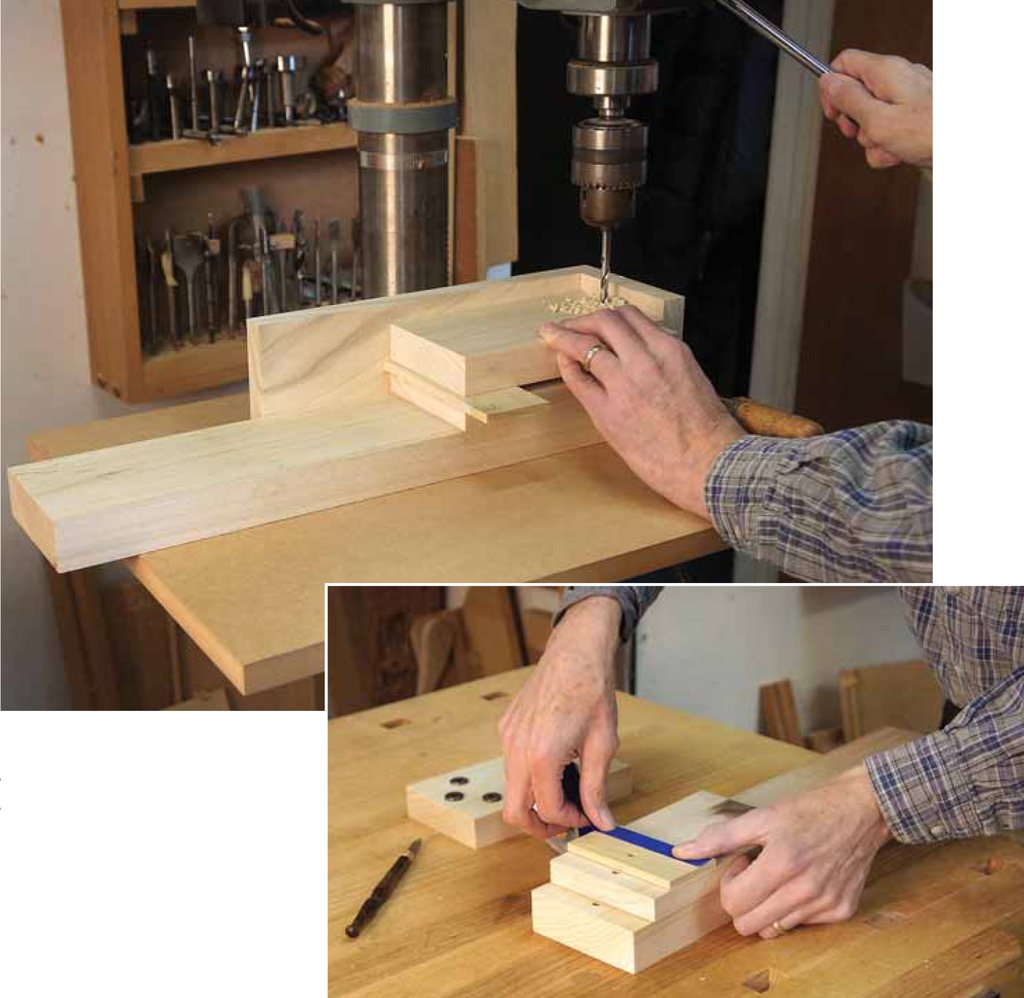
Position the parts to align the holes in all pieces. A leftover piece of spacer holds the work level. Masking tape can be used to make minor adjustments to thickness.
The UHMW strips are not always sized accurately or evenly. You can correct that by handplaning them to an exact thickness with the simple jig shown on the next page (variations in the width won’t matter). You’ll experience less flex in the plastic if you cut the strips to length before planing in the jig. The shavings are unusual, but the material planes well. Once the strips are the same thickness, it’s time to work on the rabbets for the plastic strips. This is a somewhat tedious process of bolting things together, testing the fit, taking them apart and making adjustments; often many times over.
Measure the distance between your guide blocks. Subtract that amount from the thickness of two of your UHMW strips measured together (somewhere around 3⁄4″) and divide the result in two. That should be the starting point for the depth of the rabbets.
Disassemble the guide blocks and spacer assembly, and cut the rabbets across the bottoms of the blocks to the depth you just determined by 7⁄8″ wide. Now put everything back together. There shouldn’t be any space between the UHMW strips when you slide them into place. Sneak up on exactly the right amount of space for the saw- plate by deepening the rabbets a little at a time. A router plane is perfect for this task, but you can choose whatever method allows you to take off small amounts while keeping the rabbets flat and parallel.
Once fit, the strips should ride against the saw plate without clearance. If you happen to make the rabbet too deep, you can always place shims behind the UHMW strips to bring them closer together. When you think you’re close, drill and countersink the UHMW strips for the screws that attach the strips to the guide blocks. The screws securing the UHMW plastic to the inner guide block go through the block into the upright. Be sure all of the countersunk holes are deep enough to keep the screw heads well below the surface of the plastic. Put the jig together one more time to verify the fit and make any additional adjustments as needed.
The other important part to the core of the jig is the vertical fence at the back of the upright. The 1⁄4″-thick by 1 1⁄2″-to 1 3⁄4″-wide strip should be screwed into a 1⁄4″-deep by 1⁄2″- or 5⁄8-wide rabbet. At this point, the jig is functional, and you could call it quits. But adding the support bracket makes it much easier to clamp to your workbench.
The Support Bracket
I designed the support bracket to work with most shoulder vises. A ledger strip let into the back of the bracket rests on the benchtop, and the width of the bracket makes it easy to clamp in most vises without racking. But this approach does not work with every workbench and vise setup. You may need to modify the support bracket to set up the jig at a comfortable sawing height and the most secure hold in your vise.
Cut a 1⁄2″-wide x 1⁄2″-deep dado in the upright, set 9⁄16″ from the back edge, and a rabbet to leave a matching tongue on the edge of the support bracket. Cut a 3⁄8″-wide x 3⁄8″-deep dado for the ledger strip across the back of the support bracket, 4″ up from the bottom (to allow for clearance for your vise screw). A cut-out just above this dado along the rabbeted edge will create better access for a clamp. Shape the bracket as desired, then glue and screw it into place. You should only glue about 1″ of the end of the ledger strip closest to the upright to allow for cross-grain movement.
The tenoning jig is basically finished now, and you can take it out for a test-drive if you haven’t already. But there are a few more components you should make to significantly enhance its capabilities.
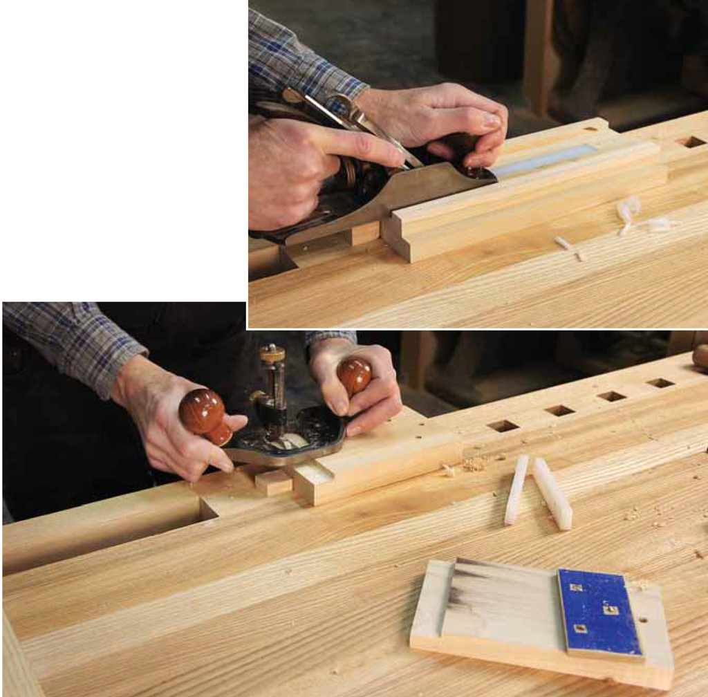
Make a simple jig to plane the UHMW strips to the same thickness. The plane rides on ledges, which stop the cut at the desired thickness. A router plane makes quick and precise work of the rabbets for the UHMW guide strips.
Most important is a set of spacers for cutting various sizes of tenons automatically. Each spacer controls the workpiece location so that both cheeks of the tenon will be cut exactly the right distance apart. This approach allows you to reference off of one face of the workpiece – much more accurate. Make one cut with the spacer in place, then remove it and re-clamp the workpiece to make the second cut.
Each of the spacers needs to be the thickness of the desired tenon plus the width of your saw’s kerf. Sizing the spacers accurately is key. Get as close as you can with careful milling. Then use packing tape, masking tape or paper in conjunction with tape to adjust for an exact fit to a mortise made with a paring jig. Once your spacer is adjusted to perfection, be sure to mark it.
One refinement that can improve the usability of the jig is a small rare earth magnet (in a magnet cup) recessed flush into the surface of the upright of the jig, and a magnet washer likewise recessed into the tenon spacers. While not necessary, it makes it easier to juggle things as you clamp the workpiece to the jig.
You’ll also need to make spacers to adjust for the tenon location on the workpiece. These can be made as necessary for various thicknesses of work and tenon locations.
The last accessory you may find useful is a set of depth stops. These are simply strips of wood thin enough to fit freely between the sawplate and one of the guide blocks. Tabs at either end help keep the stop in place. A depth stop cut to a specific width will stop the saw from cutting any deeper once the saw’s back reaches the top of the strip.
Using the Jig
Hold the workpiece (and any spacers) in place against the rear fence and up against the bottom of the guide blocks. Clamp them securely to the upright. Slip your saw between the guides and begin sawing. Keep a light grip on the saw’s handle and extend your forefinger. Align your forearm with the saw back, and cut smoothly and rhythmically until you reach the desired depth (or the depth stop). An even and steady touch will yield the best results.
Set up for the other tenon cheek by removing the tenon spacer (if you’re using a second spacer to control location, leave that one in place) and re-clamp the workpiece. Saw to the shoulder line and unclamp. Cut the tenon shoulders using whatever method you prefer. Clamping a simple guide block with a 90° fence right over the scribed shoulder line can help you pare the shoulders or act as a saw guide. Saw the narrow shoulders close to the line, then pare with a chisel that is wider than the tenon but not as wide as the workpiece.
Angled tenons? Simply make a wedge with the angle you want. Clamp the angled wedge in place in conjunction with the tenon spacer for one cheek, then remove the spacer just as you would for a straight tenon. A guide block with angled sides will help get the shoulder angles just right.
The tenon cheeks should be flat, straight and smooth. There are a number of things to check if you’re having problems. Be sure the saw slides smoothly in the jig without any slop. Fine adjustments can be made by changing the bolt tension. Next, consider your saw. Better saws usually yield better results. Regardless, you might want to check the evenness of the set. Lightly and carefully stoning the sides of the teeth can take down slight variations in set that cause a rougher surface. Finally, look at your technique. The more relaxed and steady the cut, the better the results.
Jeff is a Chicago-based furniture maker and woodworking teacher. You can see more of his work on his website.
This article appeared in the June 2012 issue of Popular Woodworking Magazine.

Here are some supplies and tools we find essential in our everyday work around the shop. We may receive a commission from sales referred by our links; however, we have carefully selected these products for their usefulness and quality.