We may receive a commission when you use our affiliate links. However, this does not impact our recommendations.
There are several cut list producing tool scripts for SketchUp. The one I have written and made available is called CutList Bridge. It produces a CSV (comma separated values) file that can be imported to Excel, OpenOffice or CutList Plus fx. Most of you are also aware that the dimensions shown in these cut lists are the overall dimensions of a component as defined by its bounding box.
 What you may not be aware of is that sometimes, depending on the orientation of the part (component), the bounding box is not optimum, or even completely wrong, for creating a cut list dimension. You also may not know that you can, or how to fix this situation and produce a correct bounding box. This is the focus of today’s post.
Examples of Incorrect Bounding Boxes
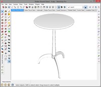
In last week’s fourth and final installment of The Book of Shaker Furniture by John Kassay – A Treasure Trove for SketchUp Generation Woodworkers I provided you the completed model of a Shaker Round Stand shown above left. Click the image to enlarge it.
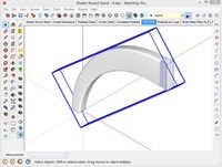 Notice there are three legs that are spaced 120° apart. If you click on a leg with the Select tool you will see a bounding box highlighted in blue. Click on image at right to enlarge. Notice that the bounding box is angled up from the red/green plane. Notice also that its thickness is the thickness of the leg, its length encompasses no more that the extreme dimensions of the leg in its grain direction and likewise its width is no more than its extreme dimensions in the cross grain direction. This makes for a correct cut list entry of 5/8” Thickness, 3 53/64” Width and 11 9/32” Length.
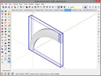 However, when I first modeled the leg, its bounding box looked like the one at left. This would have produced and incorrect cut list entry of 5/8” Thickness, 7 33/64” Width and 8 27/64” Length. There are two problems with this bounding box: first, much more material would be wasted when this part is produced; second, because of the grain direction the leg would be weak. This bounding box cries out for correction.
 Another example is shown at right. Click this image to enlarge it and look at the valley rafter. It is show selected and highlighted in blue with a corrected bounding box. Its dimensions are 1 1/2” Thickness, 11 1/4” Width and 10’ 2 27/32” Length, better know as a 2 x 12 x 10’ 2 27/32”.
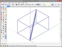 When initially modeled it may have had a bounding box like shown at left (it was too long ago for me to remember what the original bounding box was, but this is likely). The cut list entry would incorrectly be 4’ 7 15/64” Thickness, 5’ 2 19/64” Width and 7’ 6 3/4” Length. Clearly and incorrect cut list entry.
These incorrect, or unusable, bounding boxes occur most often when we model something that doesn’t align with the red, green and blue axis; which typically happens when we model something in situ. Fortunately, the fix is easy, as I will demonstrate with a short video. The tool we will use to fix this is the Context menu tool Change Axes. You must first use the Select tool to select a component you wish to correct, then right click and choose Change Axes. The following video will show this more clearly than I can explain it in words.
Here are some supplies and tools we find essential in our everyday work around the shop. We may receive a commission from sales referred by our links; however, we have carefully selected these products for their usefulness and quality.


