


We may receive a commission when you use our affiliate links. However, this does not impact our recommendations.

Super-Tune Your Tools with a Dial Indicator
By George Vondriska
Machinists use a simple measuring device called a dial indicator for setting up metalworking equipment. It works great in the woodshop, too, though for woodworking, you don't need a real fancy model. I found a perfectly adequate dial indicator, complete with all the accessories, for only $30 (see below).
The big advantage of using a dial indicator for setting up your machines is that you get instant, clear readings. The needle shows you exactly how far you've gone when you make a minute adjustment.
Let's be honest, though. Fine-tuning a machine is fussy business. Even with a dial indicator, it takes some patience and finesse. Grab a comfortable stool, and let's begin with the tablesaw.
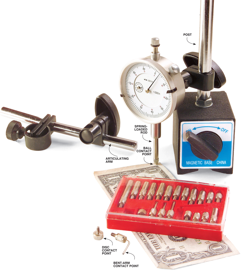
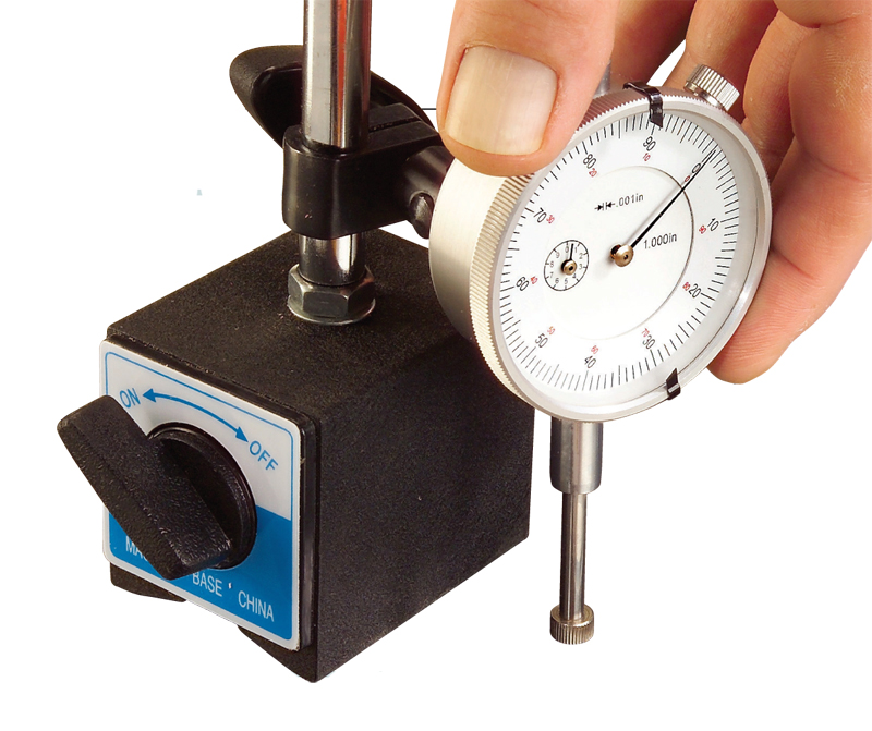
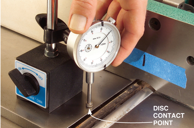
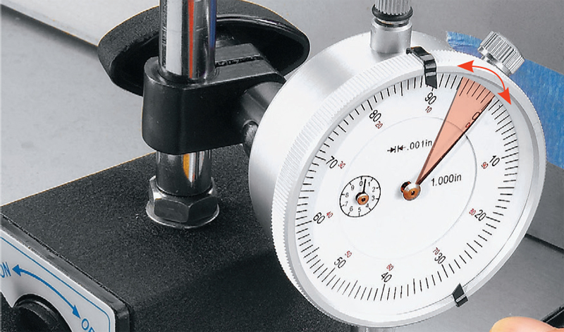
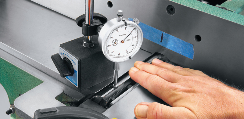
What is a dial indicator?A dial indicator is nothing more than a spring-loaded rod, a needle and a dial. Move the rod up or down and the needle rotates around the dial's face. The dial tells you how many thousandths of an inch the rod has traveled. The one at right is measuring the thickness of a dollar bill at .003 in. A complete dial indicator kit also contains a magnetic base, a long articulating arm and a set of contact points. The heavy magnetic base holds the instrument absolutely rigid on any metal surface. It's not electronic (there's no cord to plug in); you flick a switch to raise or lower the magnet inside the base. The articulating arm is used for holding the dial at a distance from the base. It's tricky to adjust, so we won't use it for these two jobs. Contact points screw onto the bottom of the measuring rod. Each one has a special shape for measuring different kinds of objects. We'll be using three contact points: a ball, a disc and a bent arm. Zero the dialThe first step in using a dial indicator is to turn the dial so the zero mark lines up with the needle. This way, you don't have to add or subtract any numbers to calculate how far the needle moves when measuring a distance. Let's practice on the top of the tablesaw. Install a disc contact point on the end of the rod and place the base on the saw. Turn on the magnet. Clamp the dial and rod so the contact point touches the table and slightly compresses the spring-loaded rod. Turn the dial to zero and you're ready to go. |
Click any image to view a larger version.
|
Tablesaw tune-up
Here we're going to make sure the blade, fence and miter-gauge slot are absolutely parallel to each other. This reduces the chances of kickback, eliminates burning and produces the smoothest cut. Install the ball contact point on the measuring rod.
If your miter gauge wiggles in the slot, you'll have to take out the play for an accurate reading with the dial indicator. Simply push the miter gauge and bar toward one side while you measure. Always push to the same side.
Align the blade to the miter-gauge slot
|
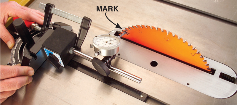
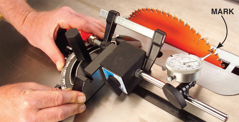
1. Turn off the magnet. Clamp the base to the miter gauge so the rod is slightly compressed when it touches the saw blade just below a tooth. Mark where the contact point touches the blade. Zero the dial. Caution: Unplug your saw for these procedures. |
2. Measure the back. Rotate the blade by hand and realign the marked spot with the contact point. If the needle has moved less than .003 in. either way, you're OK. If it has moved more than .003 in., the saw's trunnions or table should be adjusted. Consult your owner's manual for step-by-step help on aligning the blade. |
Line up the fence with the miter-gauge slot
|
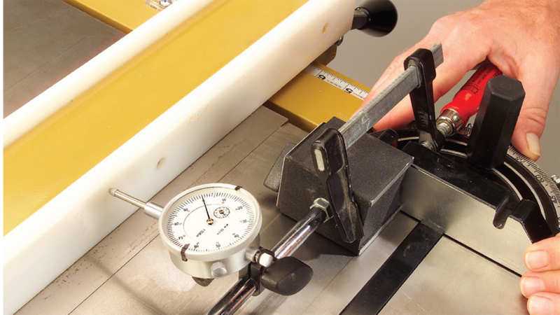
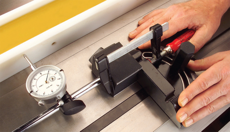
3. Measure the front of the fence. Reposition and clamp the dial indicator on the right side of the miter gauge. Slide the fence so it slightly compresses the rod. Lock down the fence. Zero the dial. |
4. Measure the back. Slide the dial indicator to the back of the fence and check the reading. If the needle is off the zero mark, adjust the angle of the fence until you get the same reading front and back. Consult your owner's manual about how to make this adjustment. |
Setting jointer knives
In this procedure, we're going to set all three jointer knives so they project the correct distance from the cutterhead and are parallel to the infeed and outfeed tables. These instructions assume you've installed jointer knives before and know the ins and outs of how to raise or lower knives and tighten them down.
If you have a knife-setting gauge for your jointer, skip ahead to Step 4. Then set the knives with your gauge and use the dial indicator to fine-tune their height.
|
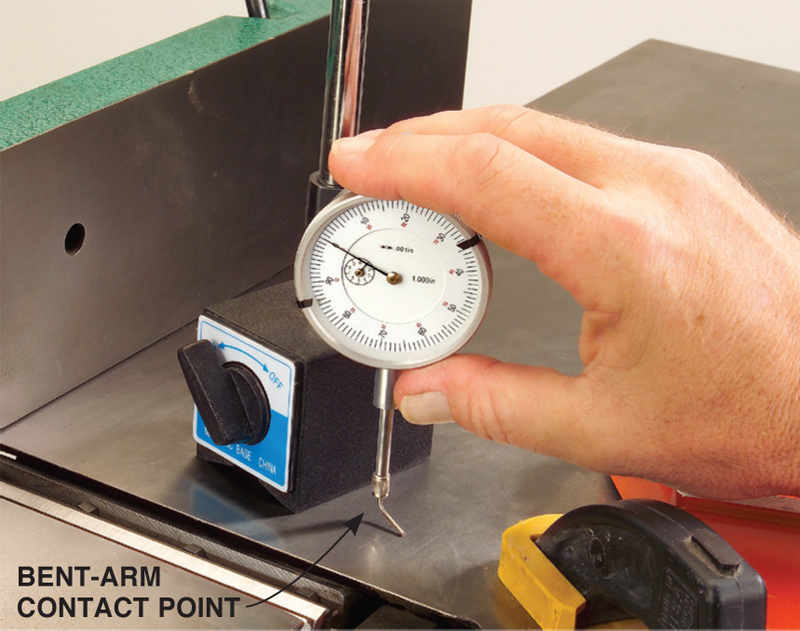
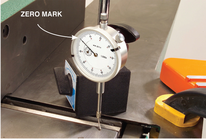
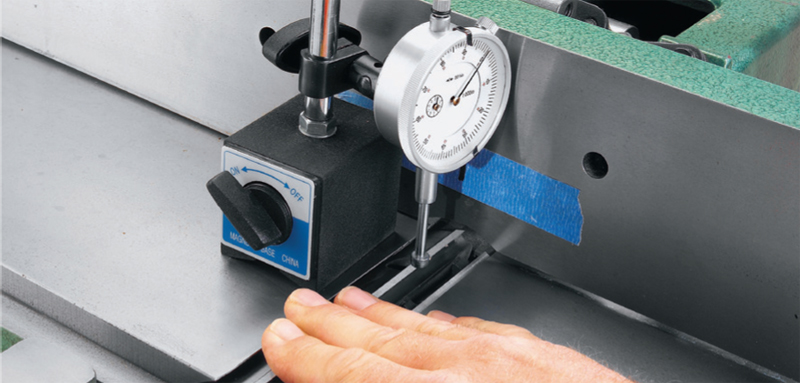
1. Zero the dial. Install the bent-arm contact point on the dial indicator. Place the dial indicator on the infeed table and turn on the magnet. Clamp the dial on the base's post so the spring-loaded rod is slightly compressed. Turn the dial to zero.
3. Level the outfeed table. Reposition the dial indicator so the bent arm touches the outfeed table. (On some jointers, you may need to use the articulating arm to reach across the tables.) Raise or lower the outfeed table until the needle reads zero. Lock the table.
5. Change contact points. Remove the bent-arm point and install the disc. The wide, flat bottom of the disc makes it the best choice for knife-setting. The disc gives you more latitude in positioning the dial indicator on the table when the knives are at top dead center. Zero the dial again.
7. Zero the right side. Rock the knife by hand back |
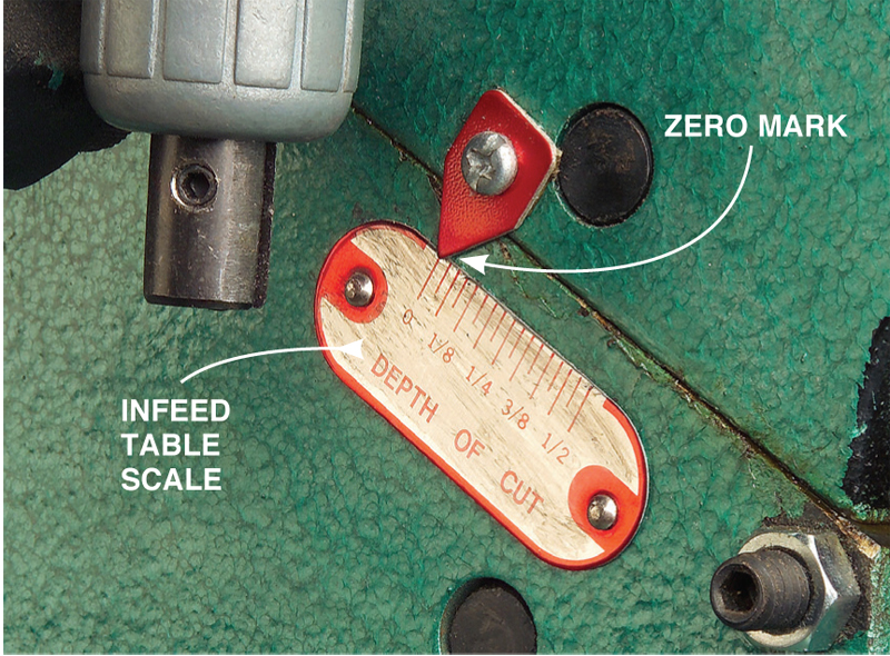
2. Zero the infeed table. Raise or lower the infeed table until the depth-of-cut scale reads zero. If you haven't reset this scale in the past, this step ensures that your knives will project the correct distance from the cutterhead. If you have reset this scale, consult your owner's manual about how far the knives should project above the cutterhead.
4. Mark the top dead center. This is the position of the cutterhead where the knives reach their highest point. Apply a piece of masking tape to the fence and place a ruler across the tables. Turn the cutterhead by hand. Mark the spot where the knives touch the ruler.
6. Position the dial indicator. Slide the fence out of the
8. Level the knife. Move the dial indicator to the |
2 tips for solving jointer problems
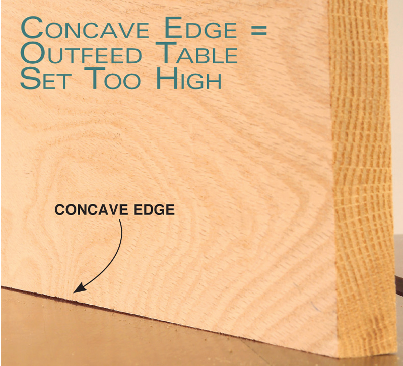
No matter how carefully you use the dial indicator, sometimes you must tweak the height of the outfeed table to get everything just right. Begin by jointing a 24-in.-long board, taking off about 1/32 in. Set the board on your tablesaw.
|
If the edge is concave, use your dial indicator to Two other problems also indicate an outfeed |
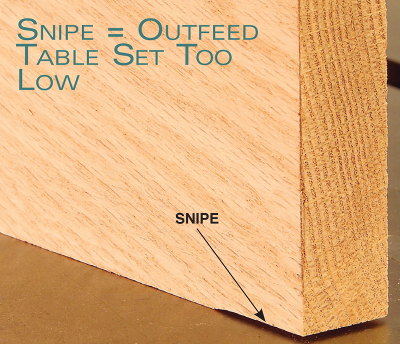
Snipe at the trailing end of the board tells you to raise the outfeed table. The snipe shown above is quite large, but sometimes it's so small you can only feel it. Raise the table in .001-in. increments until you can't see, feel or hear any snipe. |
Source(Note: Product availability and costs are subject to change since original publication date.) Little Machine Shop, littlemachineshop.com, 800-981-9663, Dial Indicator, Magnetic Base and Point Set, #1782. This story originally appeared in American Woodworker January 2005, issue #112.
|
|

Here are some supplies and tools we find essential in our everyday work around the shop. We may receive a commission from sales referred by our links; however, we have carefully selected these products for their usefulness and quality.


