We may receive a commission when you use our affiliate links. However, this does not impact our recommendations.

This millwork technique can be used to make curved parts with accuracy and ease.
Much of my recent work has been making period-appropriate arch-top sash windows for an historic building. They are 6 1⁄2‘ tall, with a 5’-diameter arch. In other words, they’re a bit larger than what you’d likely need for a furniture piece with an arched door or opening.
But no matter what your arch needs, the same techniques apply – so although I include dimensions in this article for a small, arched cabinet door, you can apply these techniques to arches of any size.
Always begin with a drawing and a given dimension – in this case, the wood is a frame for a stained glass panel I designed and made to add some visual interest to my cabinet door.
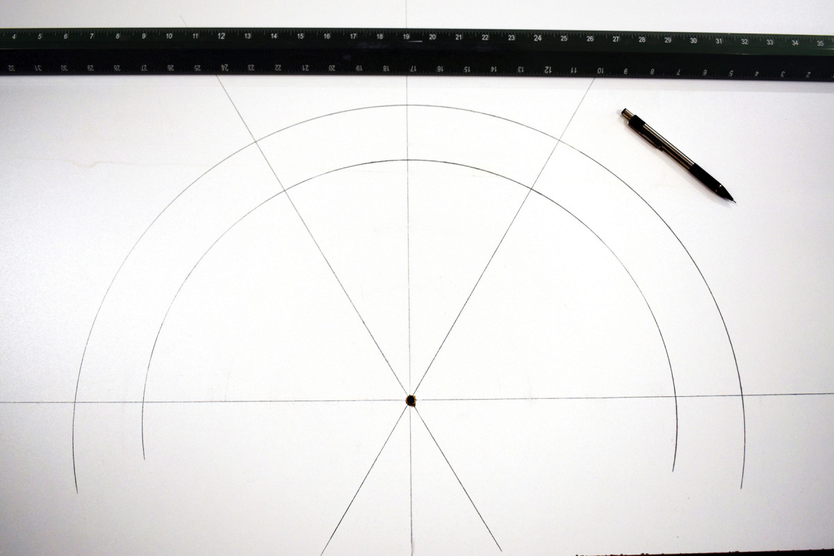
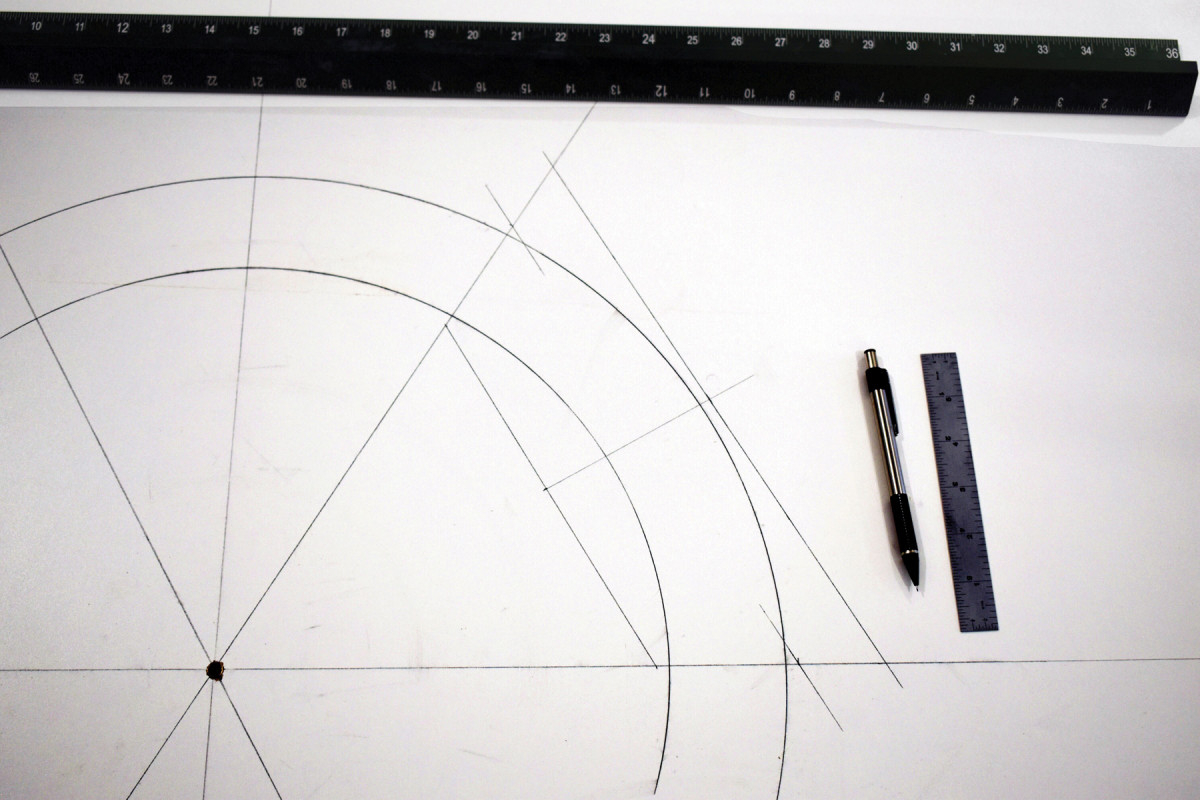
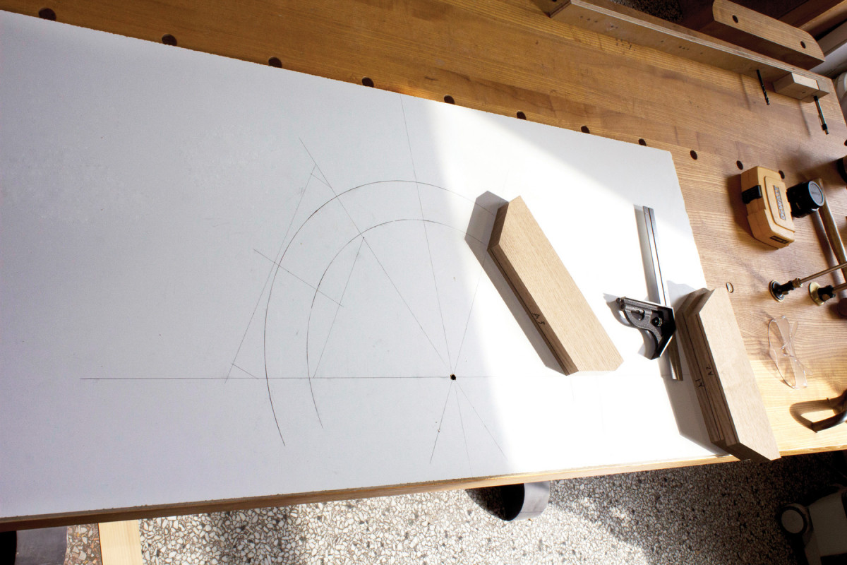
My first step is to get a 3⁄4“-thick sheet of melamine large enough on which to draw the arch. On it, I mark an X and Y axis, then drill a 5⁄16” hole at their intersection. The hole accepts a bronze bushing with a 1⁄4” inside diameter; the bushing helps to protect the much-used center pivot hole from wear.
The exterior radius of the panel is 9″, and it has 1⁄4“-wide lead caming around it, so I want a 5⁄16” rabbet to house the panel – that gives me 1⁄16” of wiggle room for hiding the caming.
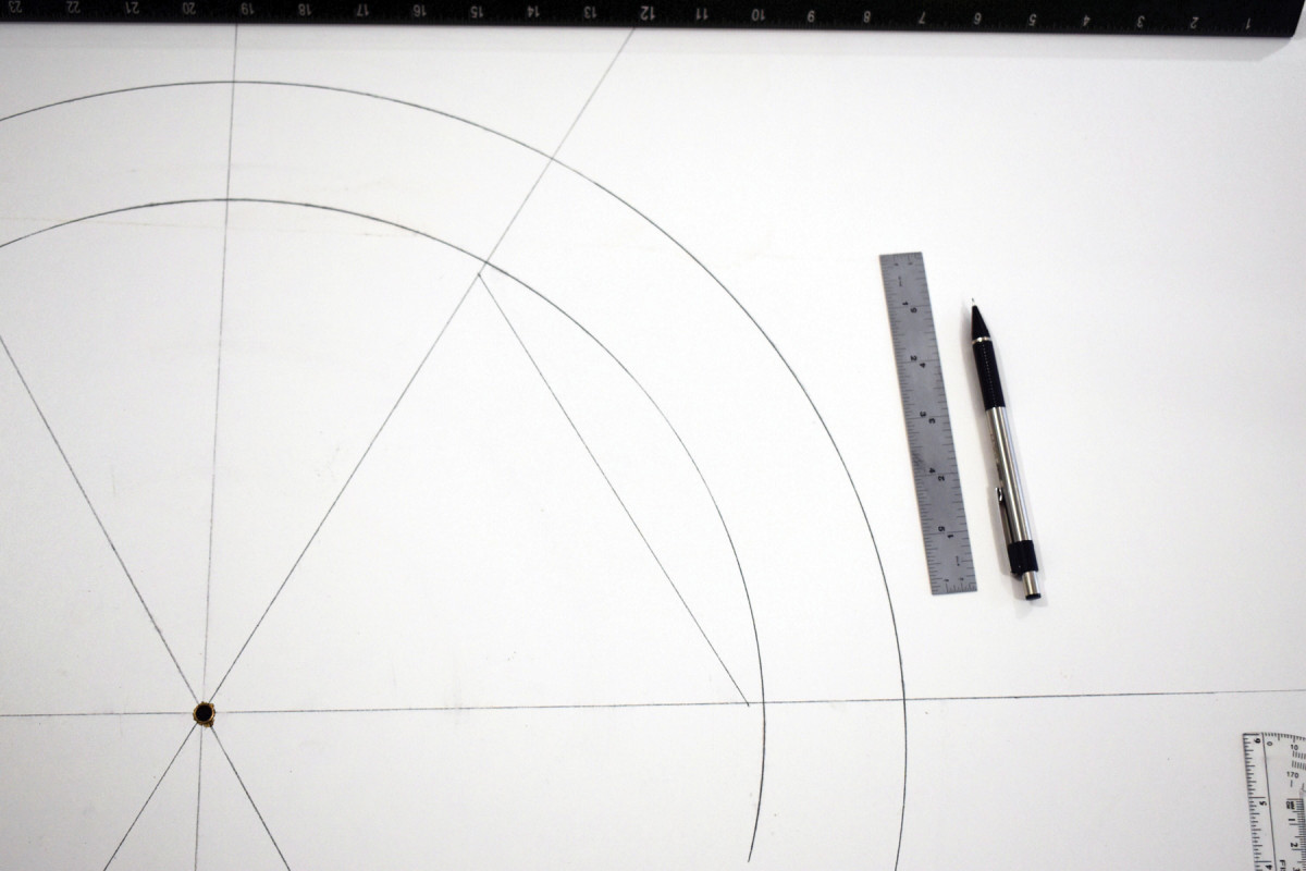
So, I drill my shop-made trammel marking jig for an 8 3⁄4” radius to scribe the internal arch on the melamine. Next, knowing that I want a 2 1⁄4“-wide frame, I drill the trammel to an 11” radius for drawing the external arch.
With the internal and external arches drawn, shift your focus to drawing out the individual mitered components that will make up the arch.
With the arch component dimensions determined the fun part – the woodworking – begins.
Arch Components
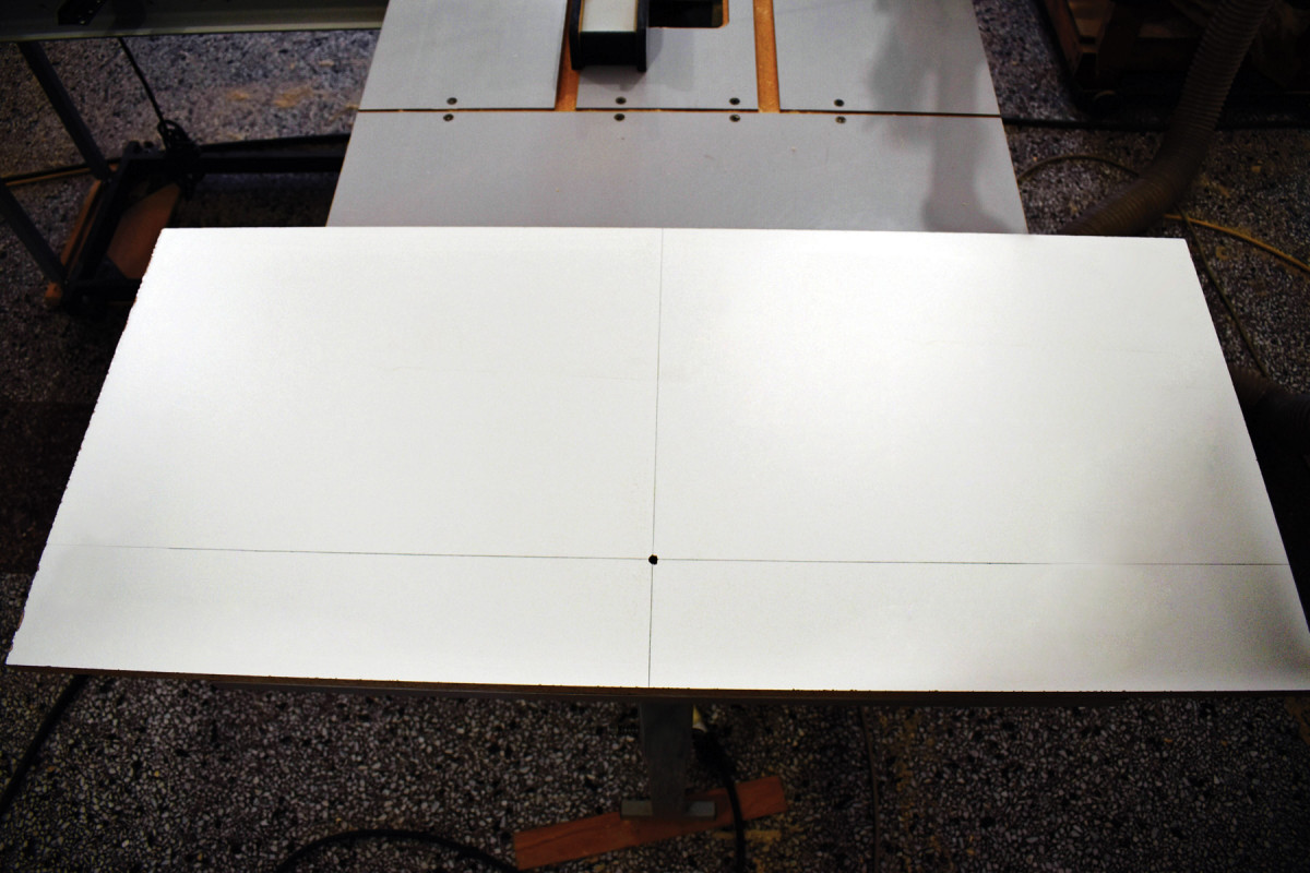
1) Draw vertical and horizontal axes on a sheet of melamine, then drill a 5⁄16″ pivot hole where they cross, and insert a 1⁄4″ inside-diameter bushing.
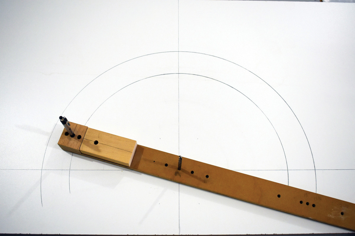
2) Make a simple trammel to draw the interior and exterior radii of your arc. A 1⁄4″-diameter drill bit makes a nice pivot.
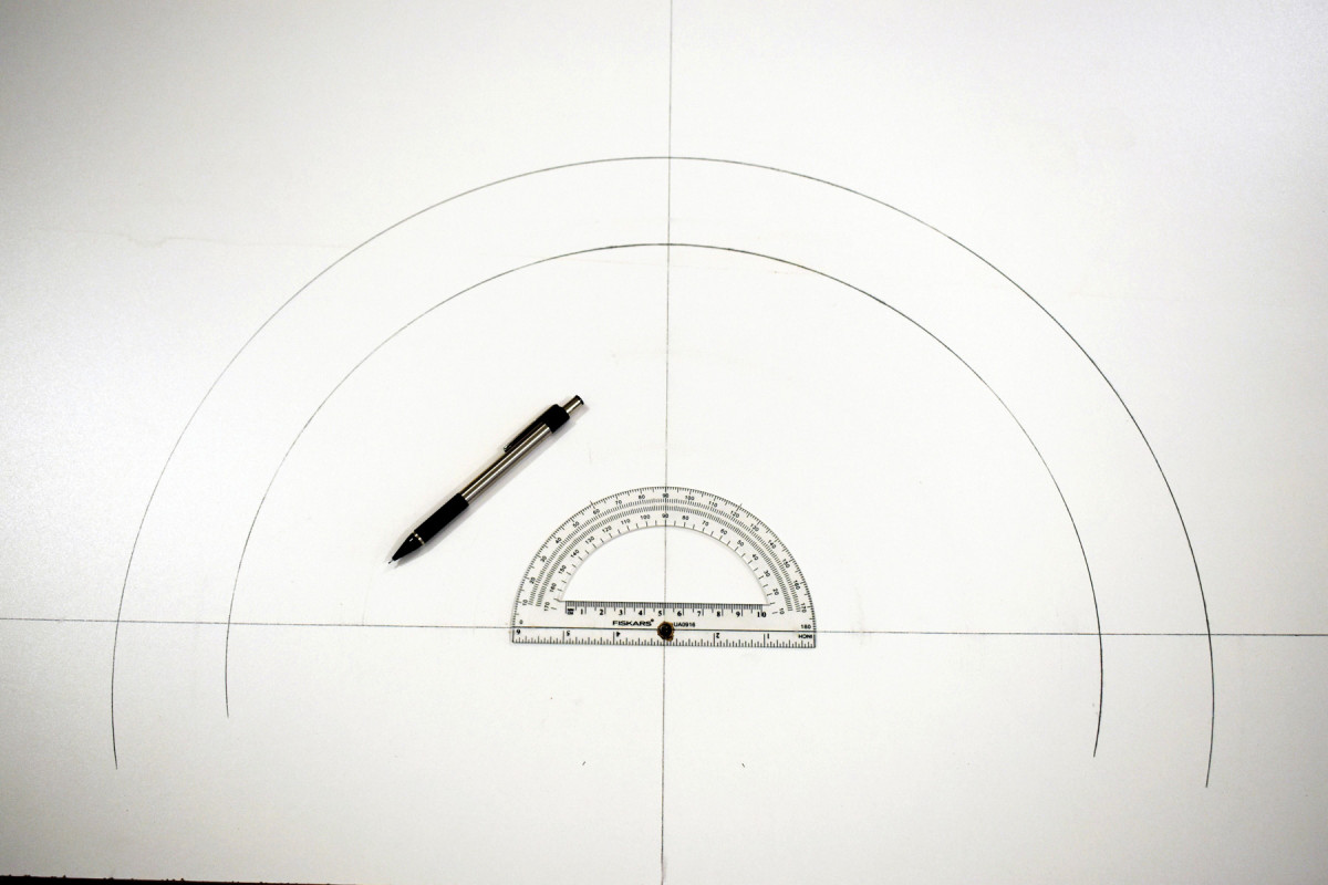
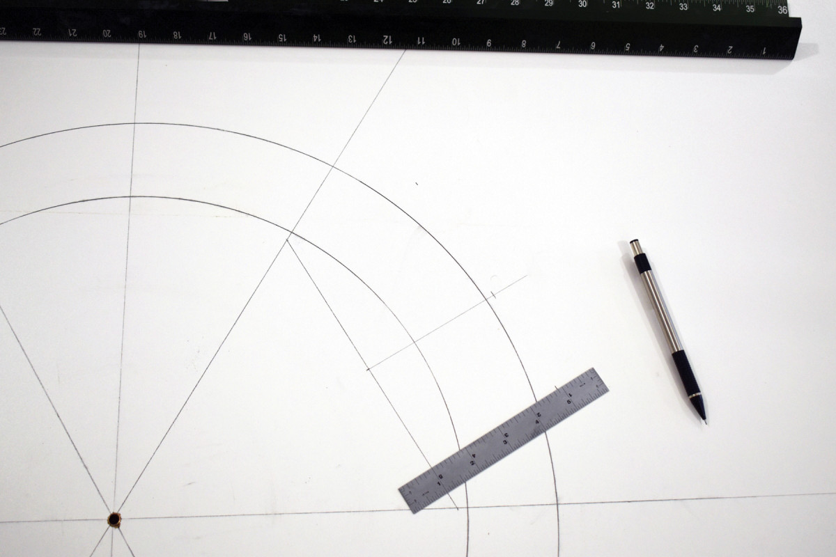
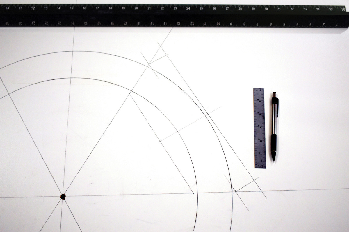
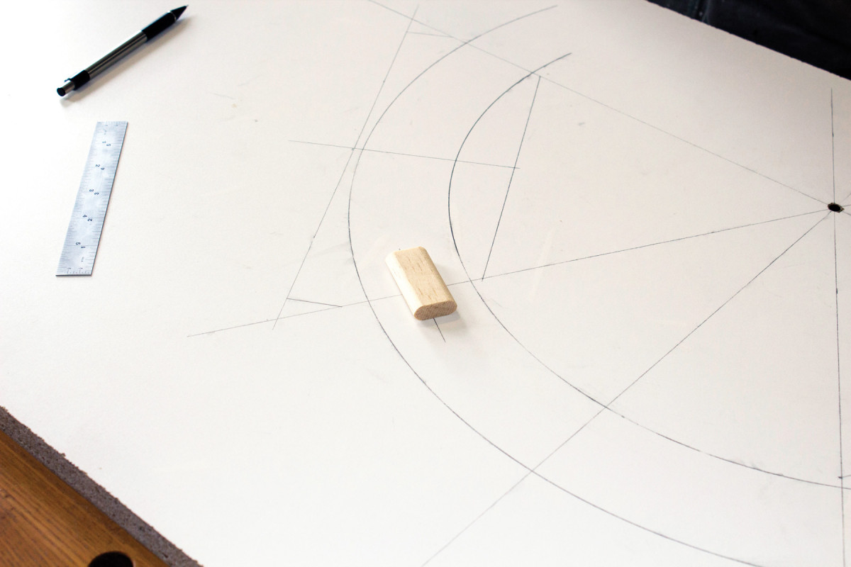
3) Mark 60° and 120° increments with a protractor to both sides of the pivot point.
4) Divide the arch into three equal segments by connecting and extending the 60° and 120° marks from the pivot point.
5) Measure 1⁄4″ from the interior radius on the horizontal and adjacent angle line, and connect the dots. This line is the interior extent of the rough frame segment.
6) Mark the center point on this line, then extend a line 90° through the exterior arc. Mark 1⁄4″ beyond the exterior arc on that line, then measure and mark equidistant to either side of that line from the interior extent.
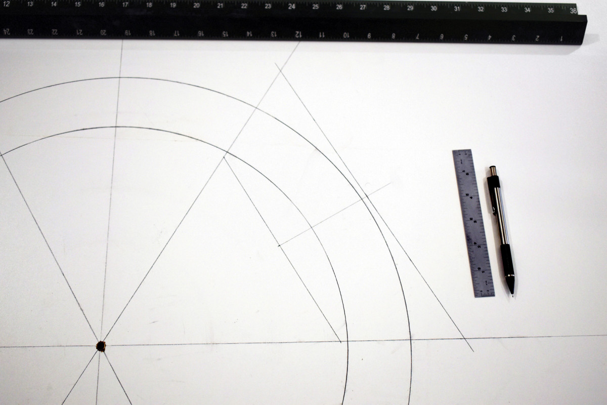
7) Connect the points to determine the exterior extent of the frame segment, parallel to the interior extent. You’ve now defined the overall segment width of the workpiece.
8) Now mark at 1⁄4″ again, this time beyond the exterior radius on the horizontal axis and 60° angle line.
9) Draw perpendicular lines from those marks to the exterior extent line. From line to line is the overall segment length of the workpiece. Note that I use a Festool Domino for the joinery; if you prefer to use traditional tenons, you’ll extend the length accordingly (for a tenon at both ends of the center piece and at the ends that mate with the stile on the two outside arch pieces).
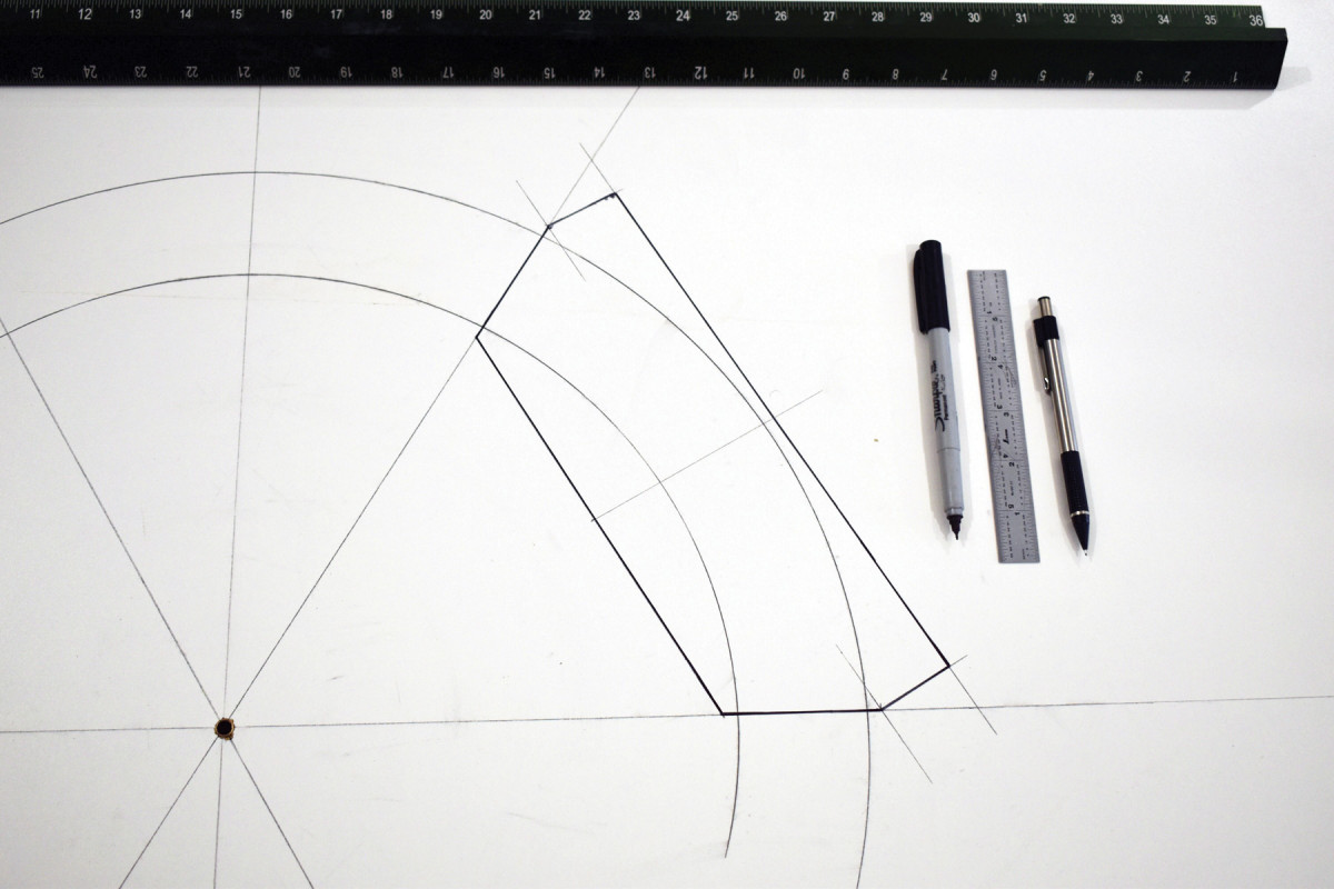
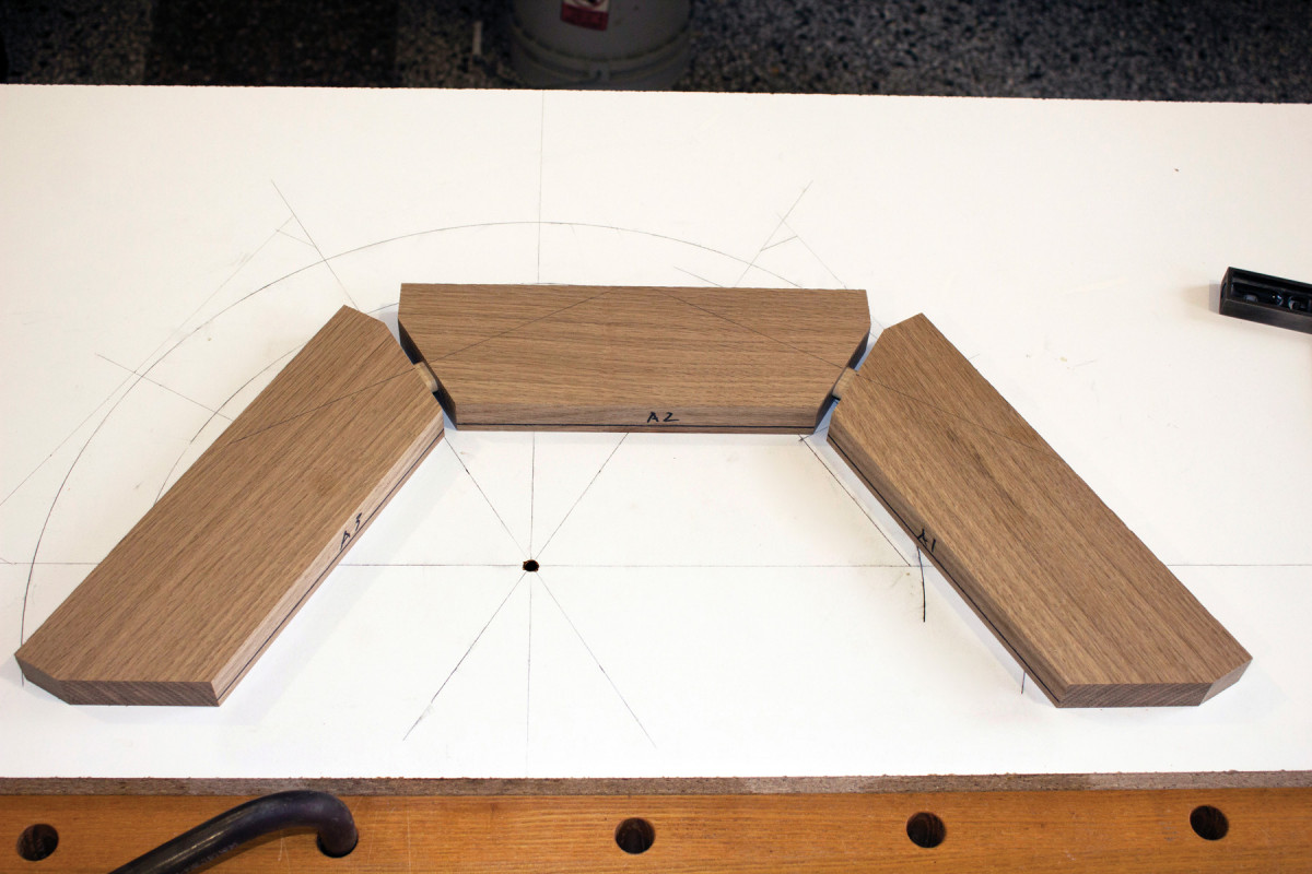
10) Three of these segments joined together, outlined here in bold marker for clarity, will make up your arch.
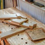
Wood Selection & Layout
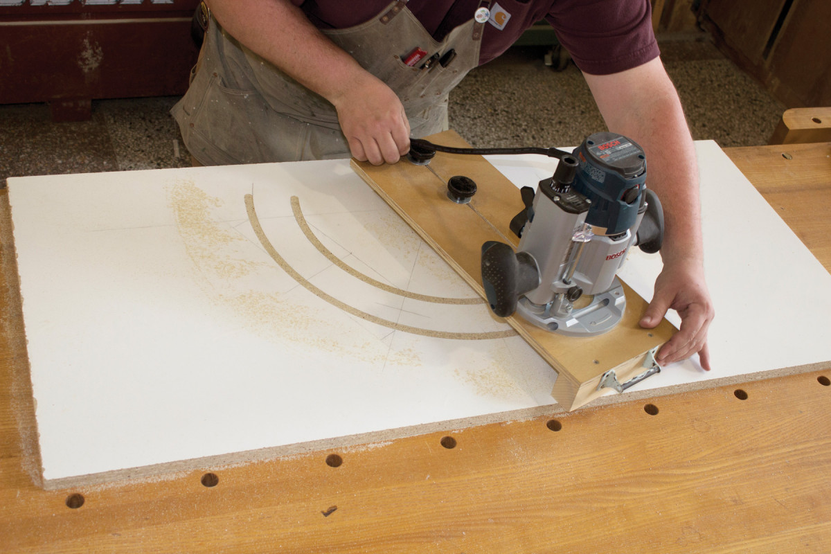
Draw the arch. Here, I’m using my shop-made trammel jig to scribe the interior and exterior arches onto 3⁄4″-thick melamine. Note the axes – where they cross, I’ve drilled a 5⁄16″ hole to accept a 1⁄4″ inside-diameter bushing. The bushing keeps the pivot point from distorting during use.
To go with the Arts & Crafts design of the stained glass panel, I’ve chosen quartersawn white oak for the frame. Ideally, I’ll get all the wood – in this case, three arch segments, two stiles and the bottom rail – from the same long board. As long as I’m careful with layout and marking, that will result in continuous grain up the stiles and over the arch to help accentuate the form.
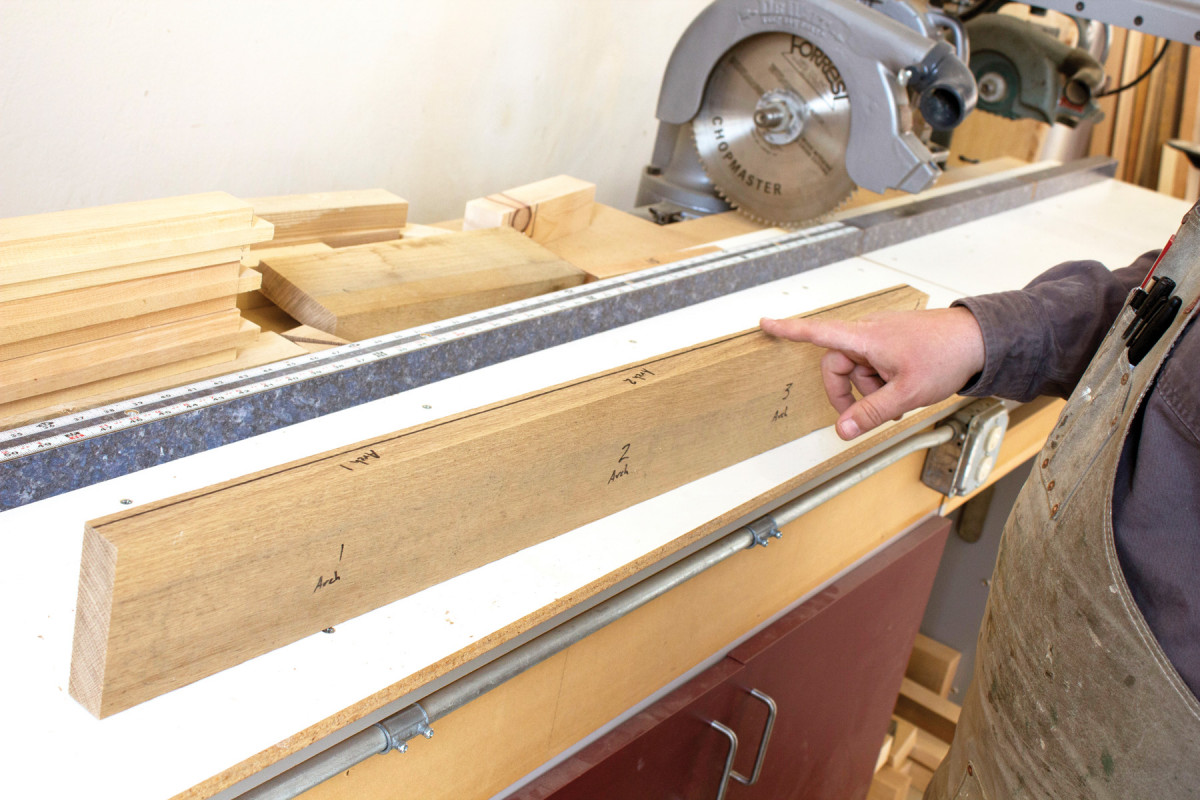
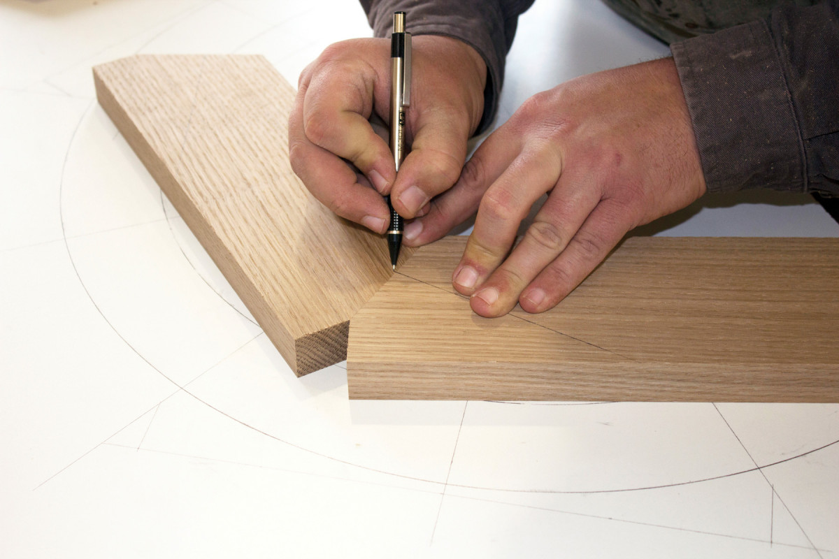
Part selection. I draw a line on one edge of the board to designate the interior edge of the parts. I also offset it closer to one face, which also indicates my show surface. You can use your own method of denoting orientation, such as marriage marks or a cabinetmaker’s triangle.
I selected a relatively quiet, quartersawn board. In this situation, I’m after straight grain, not showy ray flakes, to frame the glass rather than compete with it for attention.
I begin the layout of the rough oversized parts with the left-hand stile followed by the three components that will make up the arch (joined with loose tenons, so I don’t add length for tenons; your needs may vary), then the right-hand stile. Cut the material for the bottom rail from what remains.
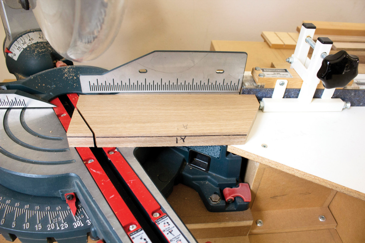
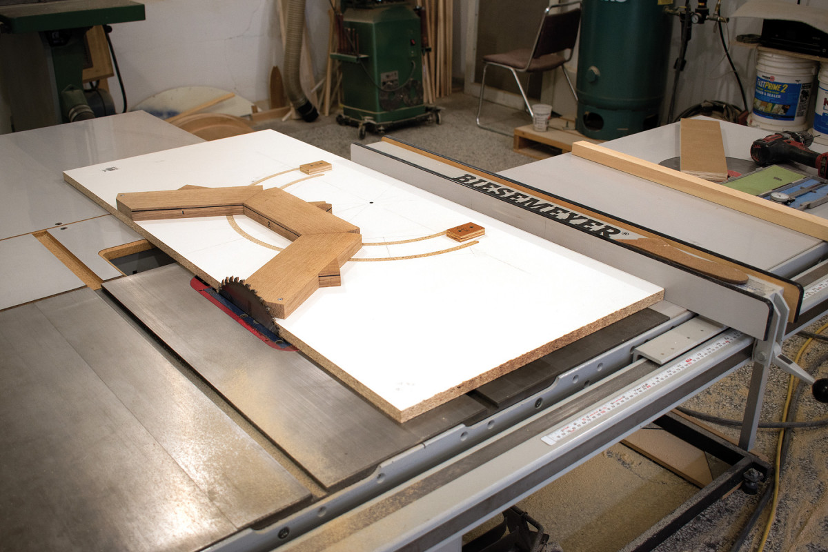
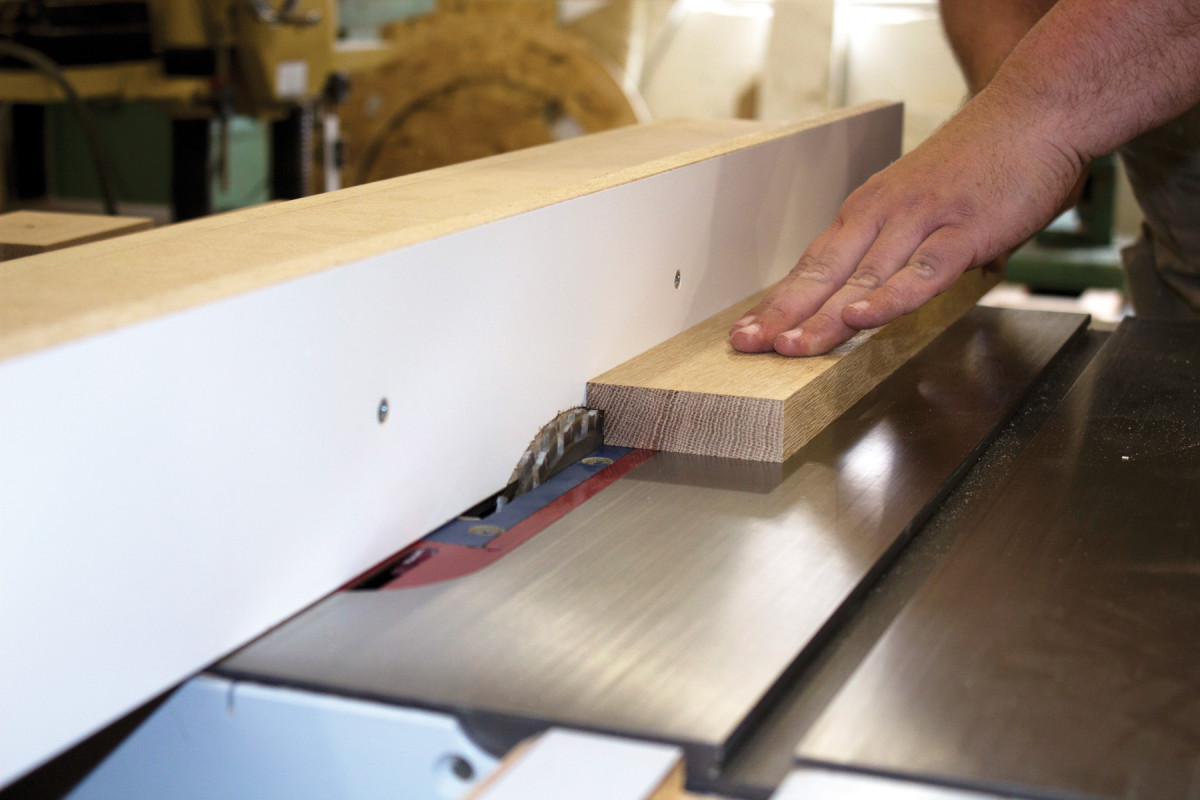
Angle cuts. I use a miter saw with a stop system to make the 30° cuts for the arch pieces. You might choose a table saw with a mitering jig or sled, or cut them by hand and shoot the edges (if you’re into that kind of thing). Regardless of how you choose to cut them, just make sure they come together tight where they’ll be joined.
Next, cut free from your board the parts that will produce the stiles and rail, but leave the three arch components connected together in their single rough piece.
As you make the cuts, continue your line onto the freshly cut end grain to keep track of which ends go together. I also use numbers to help me quickly know which parts meet where, and I use an arrow on the edge to mark the interior face; if I mark on the face itself, it will get milled off. Do what works for you – just be sure you can keep track of what goes where throughout the process.
Confirmation. After making the cuts on the first arch component, I check it against the drawing to confirm my saw settings are correct before cutting the angles on the other two arch components (again, I mark the angle on the interior faces first).
I started with 5/4 stock and milled it to 1″ thick, then cut the arch blanks (still on one board) to 37⁄8” wide, the stiles to 21⁄4” wide and the bottom rail to 31⁄4” wide.
Location, location. Mark the centerpoint of the joint, and choose a tenon size that leaves plenty of meat.
With the stock milled to thickness and width, cut the three arch components to length, which, using the process detailed in “Arch Components,” I’ve determined is 111⁄2“. As you make these cuts, mark each piece in its correct order.
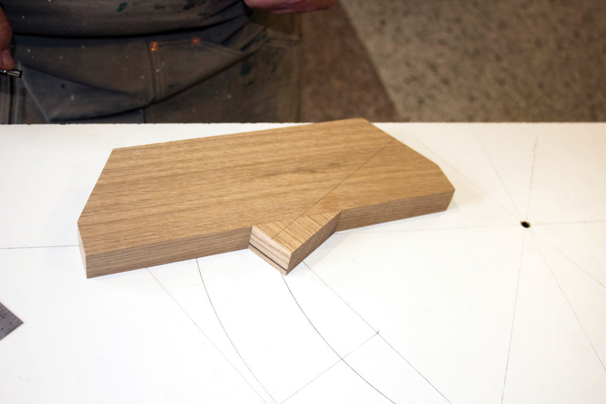
Now you’ll clip off the 30° angles using your preferred method.
Tightness of the joint is critical. Don’t stress too much, however, if the two 30º cuts don’t come together in a perfect 60º angle; just get close. After they’re glued up, any slight inaccuracies will be taken care of by shooting the two ends of the 180º arch.
Mark from the piece. Use the already-marked arch component to transfer the mortise location to the remaining two pieces, then carry those marks around with the square, perpendicular to the miter angle.
To begin the layout, mark the 30º angles on the interior side of the first arch component so that they match the arch component drawing.
I set a stop at my miter saw so the angled blade just kisses the layout line, then make the first cut. It gets flipped end for end, then I butt it against the stop and make the second cut. Then repeat twice for the other two arch components.
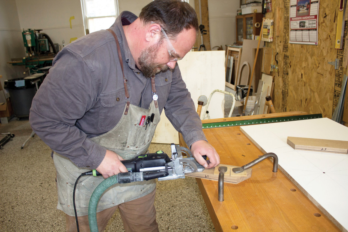
Plunge. Align the machine to your mark, then cut the mortises (one on each end of each piece).
Save the offcuts; they’ll play an important role when it comes time to clamp the joints together.
I use a Festool Domino to create the joinery. I apologize for advocating an expensive dedicated tool, but joining together parts like these is the very reason I went through the torturous pain of purchasing one. So, I’m not going to not use it. You can, of course, employ other loose tenon methods, or calculate the extra length needs during layout for traditional mortise-and-tenon joints.
With that out of the way, let’s lay out the joinery.
For that, it’s back to the drawing to mark the center point between the interior and exterior arches of the angled miter.
Check. I like to insert the loose tenons partially, and check the dry-fit against the drawing. It never hurts to be sure!
Next, you need to make sure you know which is the face side of each piece. (Remember my offset Sharpie lines? Those denote my faces.) For the rest of the build the “face” side will face down – except when cutting the rabbets on the stiles and rail.
Place the first arch component face down on the drawing and mark its mortise location from the mortise center point on the drawing.
Use a square to transfer that mark across the faces.
The remaining arch components can now be registered against this first one, again face down, to transfer the mortising marks.
The marks have a twofold purpose. The first, of course, is to reference the Domino’s cutter. The second is to align the offcut clamping blocks during glue-up.
Joinery & Glue-up
Clamping blocks. Glue the blocks in place with thick viscosity cyanoacrylate glue.
First, cut the mortises. Then it’s time for those “magical ”offcuts. What makes them magical is that no matter the angle of the miter, the offcut from it will always work as its clamping block, due to some geometric law that is best explained by someone above my pay grade.
Anyway, back to the matter at hand. The short side of the triangular offcut is the side against which the clamp will bear. Mark it at the halfway point then carry that mark around perpendicular across the top. These get aligned (then glued) with the mortise lines on the workpieces to center the clamping pressure with the mortises and their loose tenons.
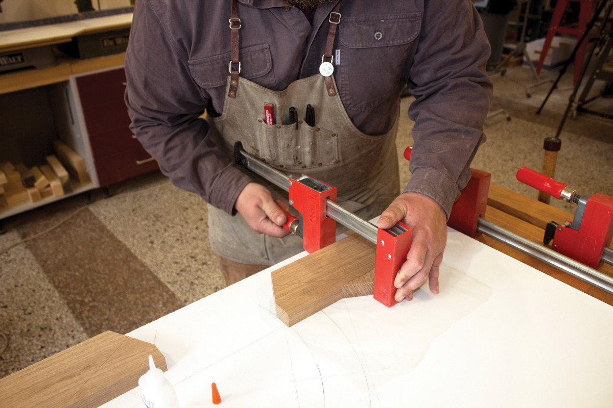
Then apply relatively heavy clamping pressure by placing the jaw at the apex.
On the center arch component, the two clamping blocks overlap each other. The fix is to cut each one where it intersects the middle of the arch component.
This glue joint is mostly an end-grain-to-long-grain joint, which just feels wrong – but it only needs to hold long enough for clamping the miters. The thick viscosity of the cyanoacrylate glue helps to prevent end-grain absorption and the heavy clamping pressure seems to help with the bond. Don’t try to use just accelerant and hand pressure – trust me.
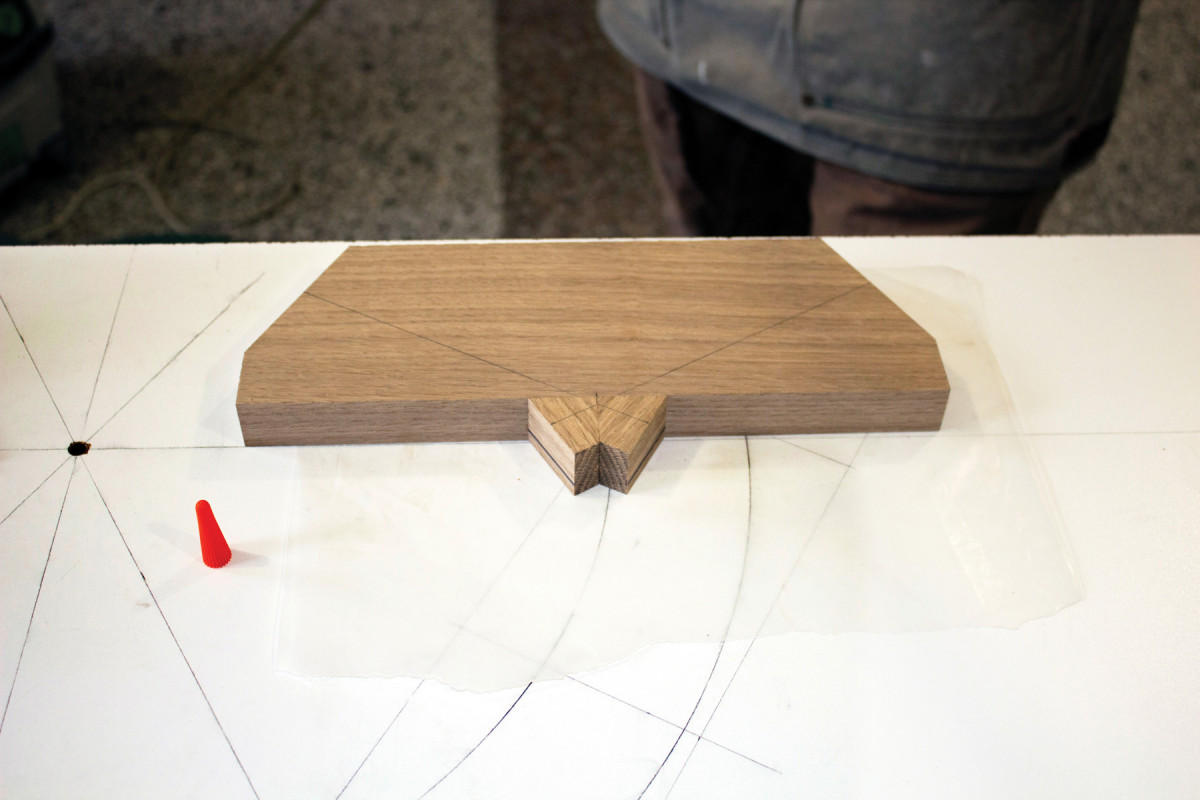
Center block. After slicing the two offcuts where they overlap, glue them together and simultaneously glue and clamp them to the center arch component.
The clamping blocks need only about 10 to 15 minutes in the clamps. Use this time to get the liquid hide glue out of your fridge and warm it up as you gather clamps, waxed paper and other accessories for the glue-up.
Once the clamping blocks are out of the clamps, use them (and those clamps!) to clamp up the miter joints.
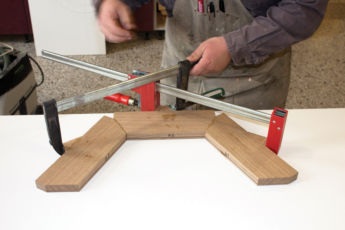
Clamp the joints. Apply glue to the ends of the loose tenons and in their mortises, then slip the joints together and clamp.
You’ll need two clamps – one with a deeper throat – to clamp both miters at the same time because they overlap.
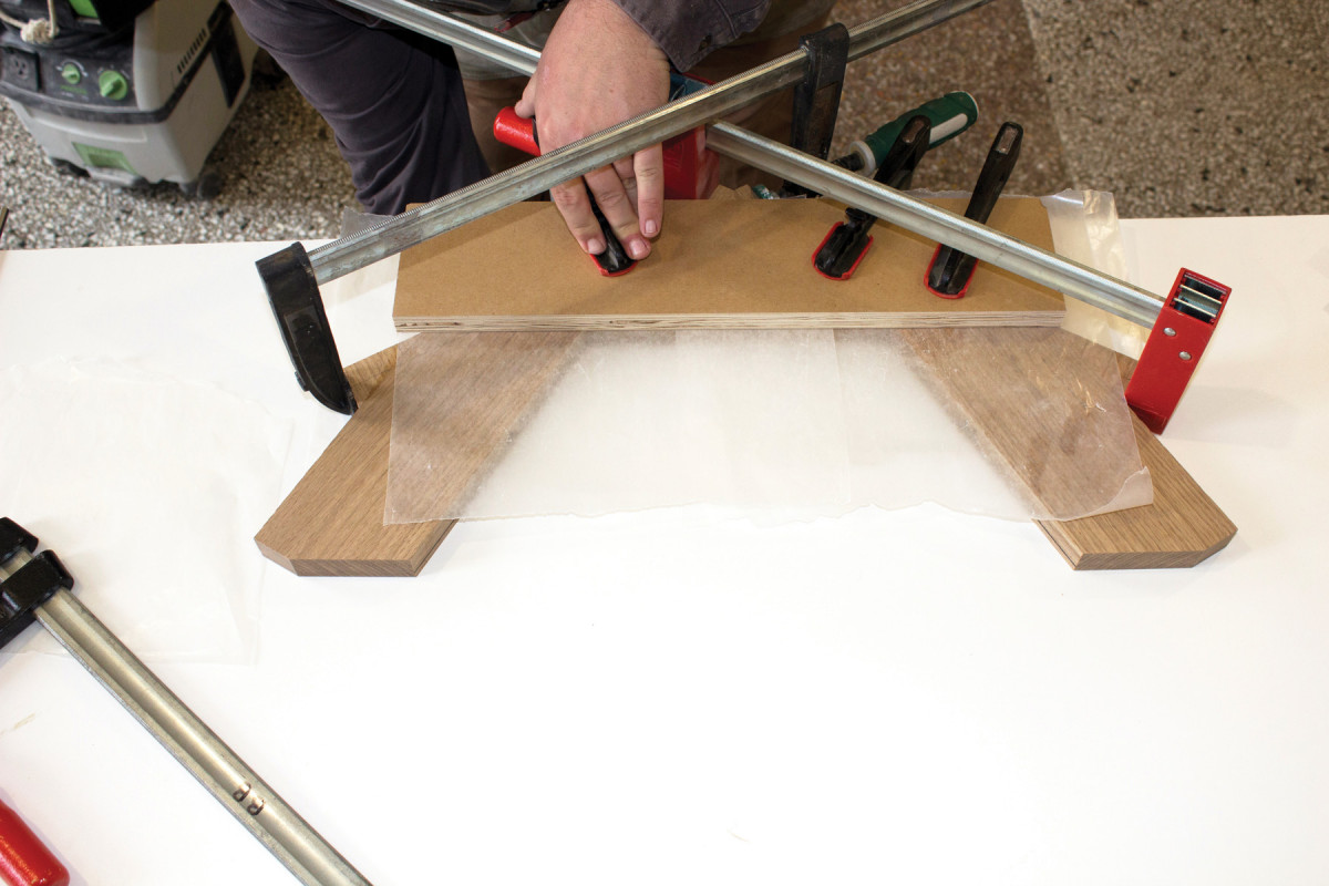
Flatten. Put some waxed paper above and below the glued-up arch, then place a caul on top and clamp that to a flat surface. It may not be necessary, but it doesn’t hurt to ensure you’ve not introduced twist from clamping pressure.
That’s a good excuse to buy a deep throated clamp…or just glue the arch up in two sessions. Either way, get the miters clamped up tight. Then clean up the excess glue before throwing some waxed paper above and below it so it can be clamped down flat with a caul on top and a piece of melamine underneath.
Flatten. Put some waxed paper above and below the glued-up arch, then place a caul on top and clamp that to a flat surface. It may not be necessary, but it doesn’t hurt to ensure you’ve not introduced twist from clamping pressure.
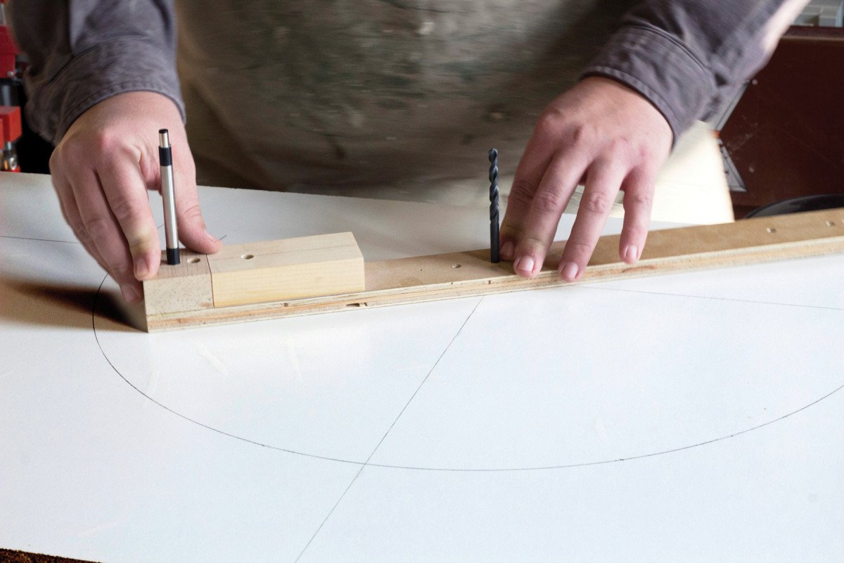
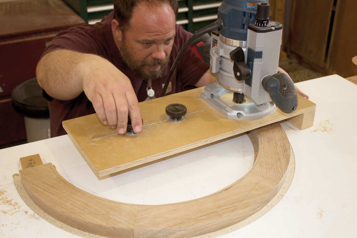
While the glue dries (you should leave the arch clamped at least overnight), turn your focus back to the melamine. You’ll use an adjustable trammel router jig to shape the arch with a 1⁄2” upcut spiral bit. But first, use it to cut two shallow grooves through the melamine’s top layer to create a “spoil board” (a sacrificial worksurface). Make the cuts on the waste side of both the interior and exterior arch radii.
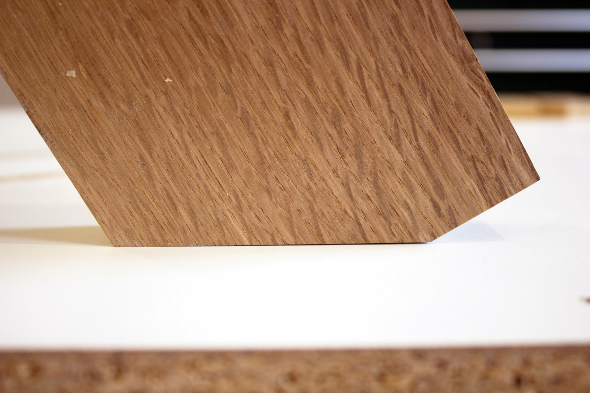
Nip it. Screw the arch to the melamine with the ends hanging just over the edge, then run it over the table saw to create co-planar flats.
Now screw two stop-blocks along the X axis to allow for registration of the arch.
Spoil Board
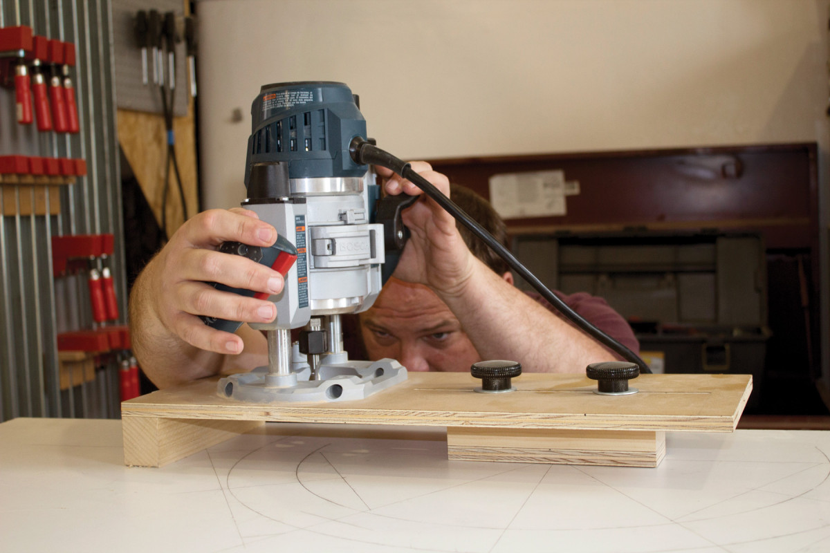
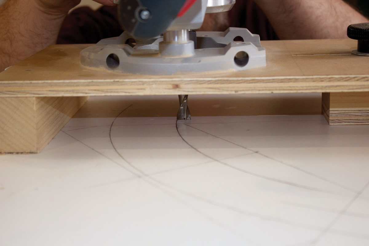
Spoil board. Cut shallow grooves on the interior radii of both arcs. The two locking knobs on my jig allow me to easily move it in or out to match the radius; the plunge router provides the necessary depth of cut.
 Get Ready to Rout
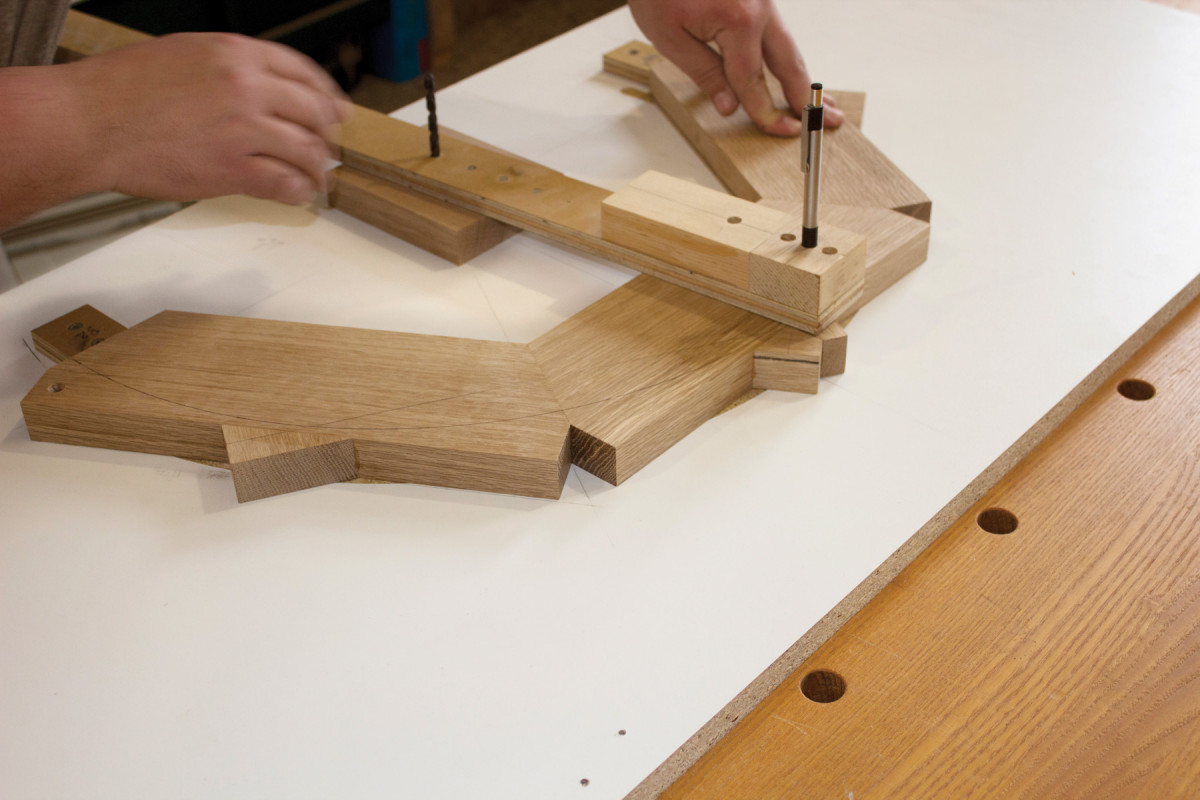
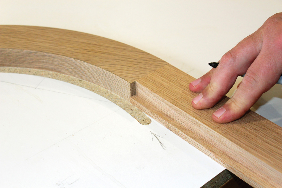
Re-mark. Use a 1″-thick riser block (to match the thickness of your workpiece) to draw the interior and exterior radii onto the arch.
Take the arch out of the clamps, then drill a clearance hole through the waste at each end. Hang the ends of the arch just off the edge of the melamine spoil board, opposite the layout. Secure it through the holes with screws, then pass the board through the saw to just nip its edge, and bring the two arch ends into the same plane.
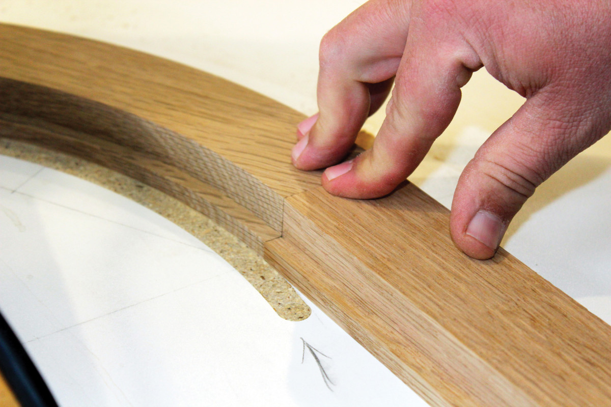
 The freshly nipped ends can now be registered and centered up against the X axis stop-blocks on the spoil board. Use the drawing trammel to mark the arch on the workpiece.
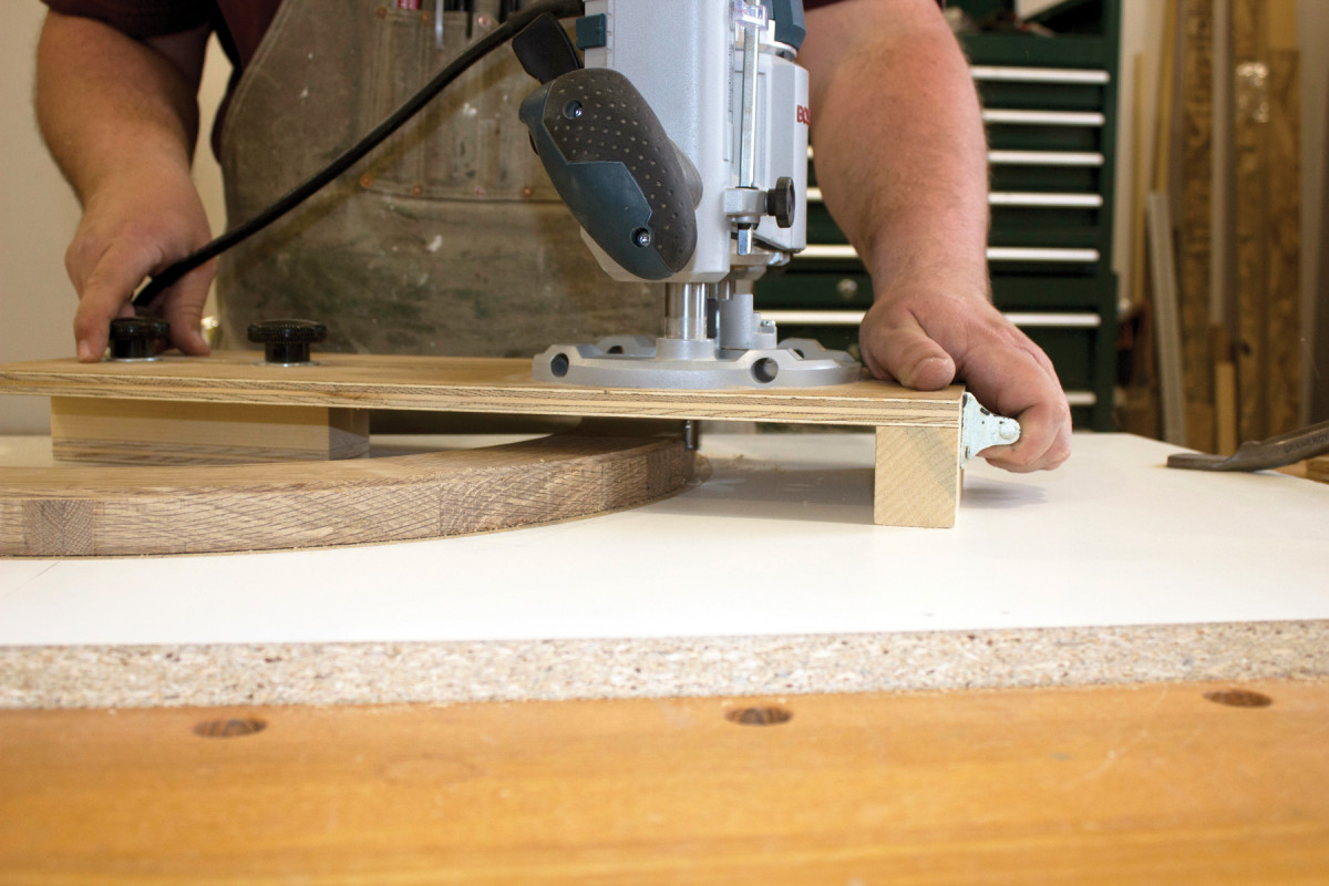
Outside first. Take a series of shallow cuts to shape the outside edge first, then do the same on the inner edge, as shown at left.
Rough out the arch at the band saw, then secure it between the grooves on the spoil board, face-side down. I use double-sided tape for this, applying heavy pressure as I push it in place, along with a few mallet taps (delivered through thin scrap to protect the workpiece).
Straight rabbets. Before routing the rabbet in the arch, I cut the rabbets on the stiles and lower rail at the table saw with a dado stack and sacrificial fence.
Now you’re ready to rout. The depth of cut and one of the radii should still be set from cutting the spoil board grooves. Make a series of progressively deeper climb cuts, about 1⁄8” deep per pass, to shape the arch. The combination of the shear cut of the spiral cutter and shallow climb-cutting passes helps to prevent tear-out on uphill grain sections of the arch.
Rabbet transfer. Align the stiles with the bottom of the arch and transfer the rabbet to the end of the arch on both sides. You’ll of course have to reset both the depth of cut for the rabbet and the router location for the rabbet radius – which you can do off the marks you transferred from the stiles. After dialing in the settings, a few passes and the curved work is complete.
With the first radius cut, reset the cutter to the other groove in the spoil board. Again, make a series a progressively deeper cuts to shape the arch.
Matched up. After routing the rabbet in the arch, check it against the stiles – just in case.
It’s rabbet time – but instead of just jumping in and cutting one on the arch, I find it’s better to first cut the rabbets on the straight pieces.
This is straightforward work, but be sure cut the rabbets on the interior edges..
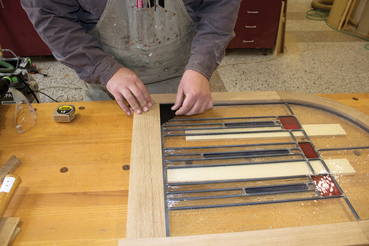
Now unscrew the stop-blocks on the spoil board so that you can align the straight pieces to the arch to transfer the rabbet.
Reinstall the stop blocks on the spoil board, then confirm that your glass panel fits inside the arch’s rabbet. If all is well, remove the arch from the spoil board.
Cut the lower rail to length, marked from the bottom of the arch.
We’re running downhill now!
Tenon the two stiles to the arch’s ends (I again used Dominos for this). Drop the glass into its rabbet, slide the lower rail into position against the panel’s bottom edge, then mark the mortise locations.
Glue the loose tenons in place, then clamp across the rail and where the arch meets the stiles. Then clamp from top to bottom.
Clean off any excess glue, then clamp the assembly flat just like before, using cauls and waxed paper to hold everything down flat onto a sheet of melamine.
Now Just Add Glass
Mortise locations. With the glass in place, butt the rail into position and mark the mortise locations. I’m using a triangular plastic piece with a 90º corner to ensure the rail is square.
Only a few tasks remain once the glue is dry: finish planing (or sanding) and applying a finish.
If you assembled your frame from continuous grain, congratulations – you get to handplane. Otherwise, get out the sander.
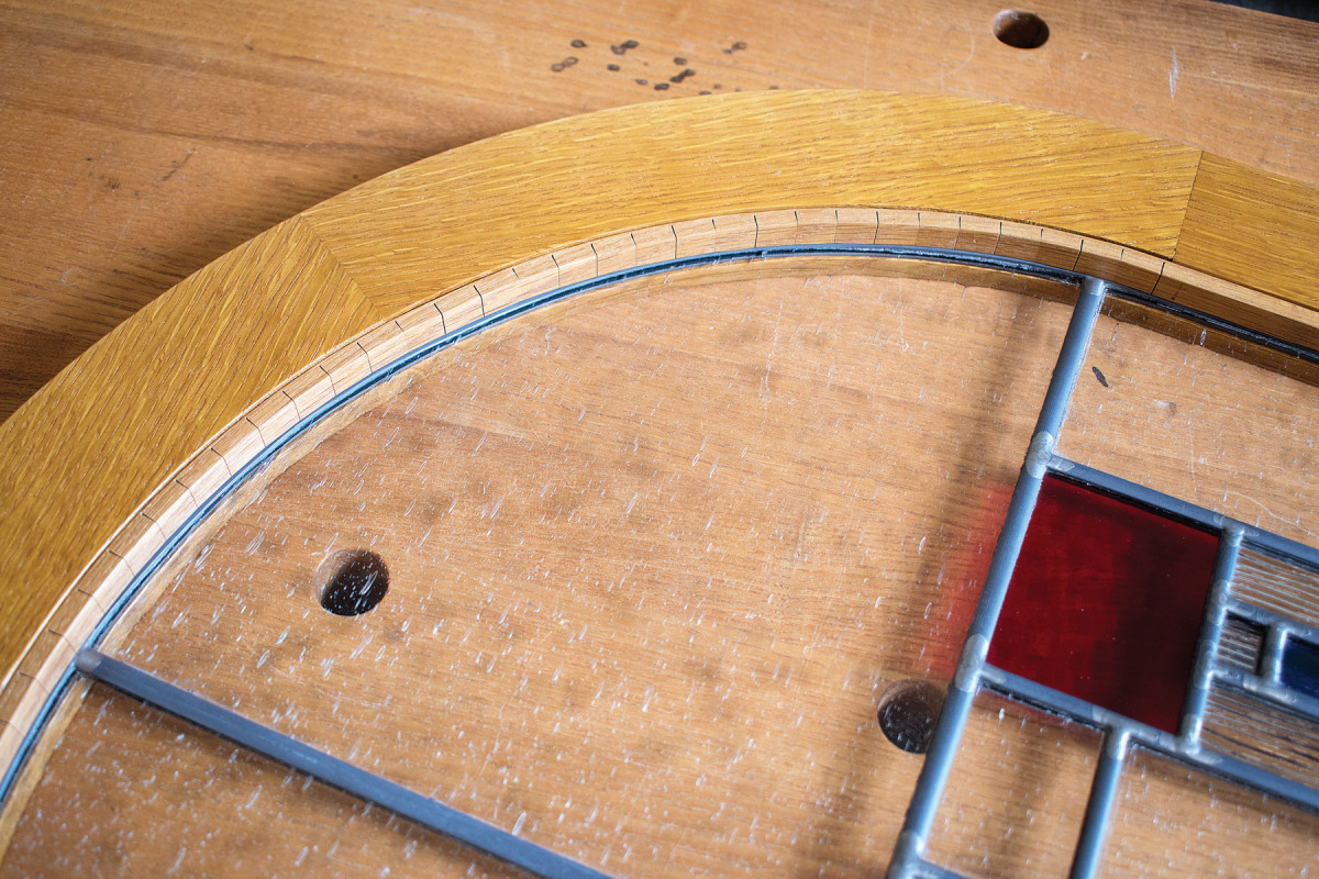
Trapped glass. Here, you can see the relief cuts in the white oak strip that is pinned in the rabbet to secure the glass panel in place.
I don’t know what’s going to happen to this door (stay tuned!) so I just used a couple coats of amber shellac as the finish. It can be topcoated with a future finish, or be easily stripped with alcohol.
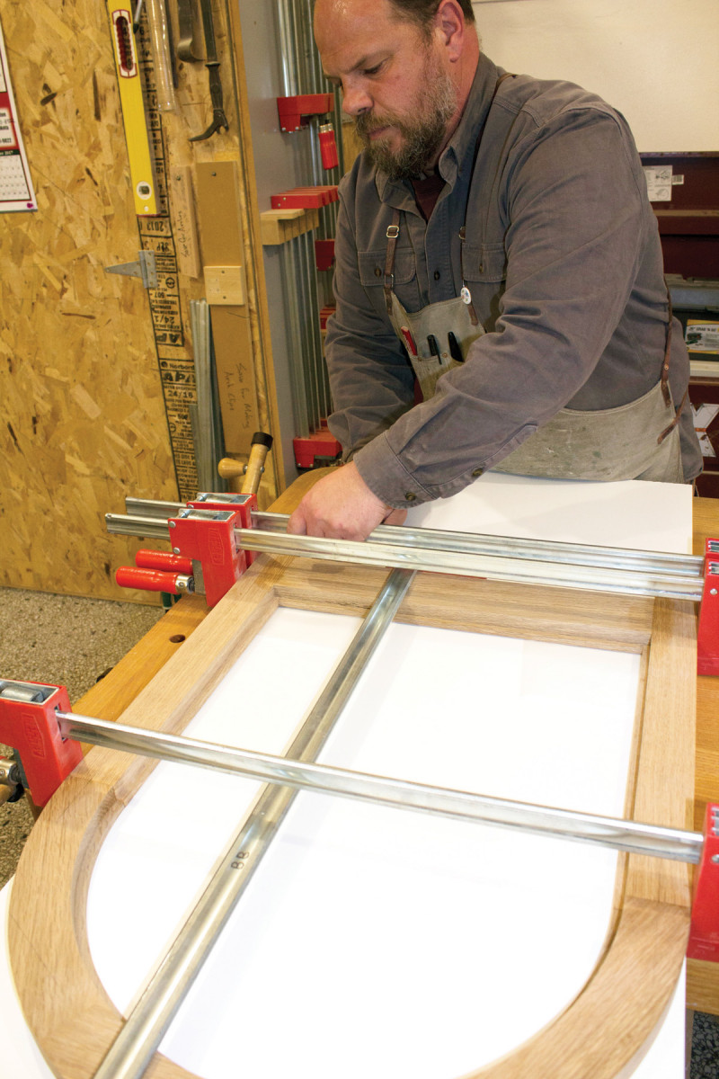
Final clamp-up. Clamps across the rail pull the joint together side-to-side, while a single clamp at the apex of the arch pulls the rail into place vertically. A clamp across the intersection of the stiles and arch keeps the joints in the arch together under this pressure.
Finally, it’s time to for the glass panel. I use white oak retaining strips to trap it in place. Thin relief cuts every 1⁄2” allow it to bend to conform to the radius. I use a thin-plate Japanese saw and a bench hook to cut these.
The strips are secured with a (carefully aimed) 23-gauge pin nailer.
Here are some supplies and tools we find essential in our everyday work around the shop. We may receive a commission from sales referred by our links; however, we have carefully selected these products for their usefulness and quality.