We may receive a commission when you use our affiliate links. However, this does not impact our recommendations.
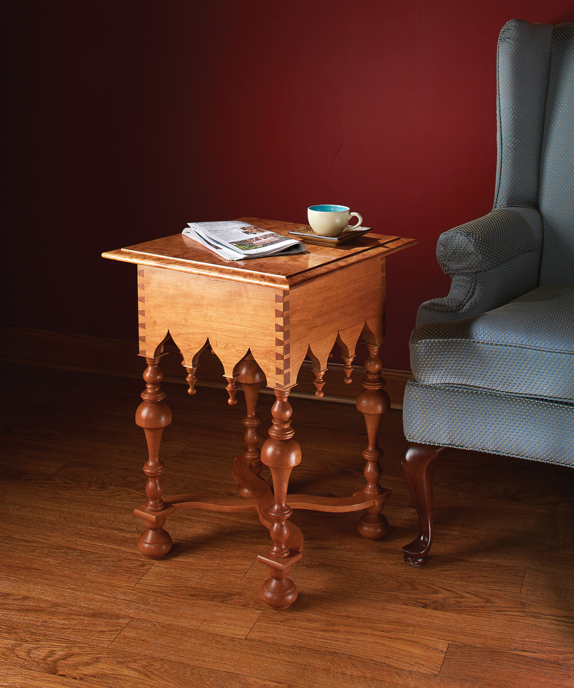
 Turned drops and legs, arches, and serpentine stretchers typify this ornate 17th-century style.
 Turned drops and legs, arches, and serpentine stretchers typify this ornate 17th-century style.
When someone uses the term “period furniture,” we think most often of the Queen Anne, Chippendale and Federal genres. Certainly these have been the most influential styles in Western furniture-making history. But there have been other periods worthy of our attention, among them the William & Mary period, named for the English monarchs of the late 17th century. This is a genre I’ve long admired. Unfortunately no one had ever before asked me to build in this style, so when my wife asked for a small table on which she could rest her coffee cup beside her bird-watching chair, I decided to indulge myself.
The design of my wife’s table incorporates several William & Mary motifs: the serpentine X stretcher, the Gothic arches on the apron, the turned drops at the bases of the arches and, of course, the bold leg turnings, incorporating both the “cup and trumpet” and the bun foot features.
William & Mary Side Table Cut List


Drawings & Story Sticks
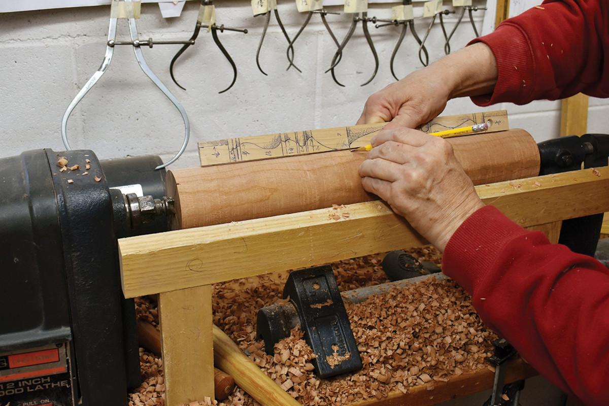
Story stick. Locate the position of the leg’s greatest diameter, leaving sufficient material north and south. Note the row of calipers on the wall, each set to one of my final turning dimensions; I leave them set until I’m done turning all like parts for a project so that I can quickly and easily check the diameters.
I begin the construction of any piece of furniture by creating measured drawings to guide me through the construction process (presented here in 1⁄4 scale). Then, based on those drawings, I make my patterns and story sticks. This particular table requires three story sticks: one for the legs, another for the feet, the last for the drops. It also requires a pattern for the Gothic arches of the aprons and a pattern for the X stretchers.
In addition, I made two simple measuring implements: one for the legs and one for the feet. These are necessary because it isn’t possible to lay a story stick or a rule on a “bold” turning and produce accurate results – the peaks and valleys of the turning make it impossible to lay the story stick flat on the work. And, while the heights of intermediate turned elements can vary from leg to leg or foot to foot, it is critical that the overall length of these parts be absolutely consistent from one to another.
I don’t keep pattern material in my shop. Instead, I use whatever odd pieces of wood that will serve, so for this table my story sticks are hardwood offcuts; my patterns, two pieces of 1⁄4” plywood; and my measuring gauges, are two pieces of 3⁄4” pine.
At the Lathe
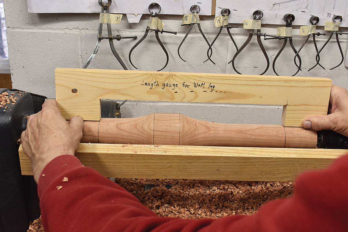
Location, location. After you’ve reduced the diameter of the top and bottom of the leg blank, use the story stick to mark the shoulders at the top and bottom of the leg. Then nail down those locations with your length gauge. Note that I allowed a tiny bit of extra length between the shoulders to remove when the turning was done.
The most eye-catching feature of William & Mary furniture is the use of bold turnings. The word “bold” doesn’t refer to a quality the turner brings to the process (if it did, I would be disqualified). Instead it refers to turnings in which there is a considerable difference between the greatest and least diameters. For example, the upside-down “cup” above the “trumpet” has a diameter of 3″, while other parts of the leg turnings have diameters as narrow as 3⁄4“.
Begin the turning process by establishing an order for the steps you will take to produce these parts. In the case of the legs, I first turned my 31⁄8” square turning stock into a 3″ cylinder with a roughing gouge.
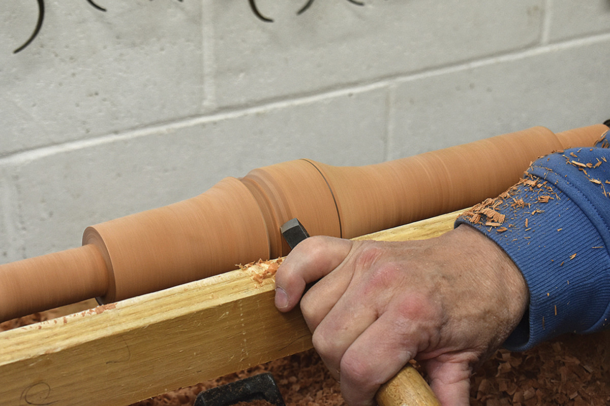
Turn, turn, turn. I turn beads and any bead-like forms (the cup above the trumpet, in this case) by rolling the tip of a 1⁄2″ skew over the side of the bead. (You can also use a gouge.)
I then marked the bottom of the cup (the point of greatest diameter). Next, I reduced the length below that mark to 13⁄4“, the greatest diameter of any element in that section, and I reduced the diameter above the cup to 2”, the greatest diameter in that section – keeping in mind, of course, the tapering shape of the cup above the mark.
For cove-like shapes, such as at the top of the bottom vase here, I use a 1⁄4″ gouge, keeping the bevel on the work.
After estimating the placement of the tenon shoulders with the story stick, I used my length gauge to nail down the overall distance between tenon shoulders. With a parting tool, I cut a trench on the outside of both marks to a diameter of 1″. This is twice the diameter of the finished tenons, but it’s enough to establish the limits of the visible parts of the leg, and leaves more meat to support the piece during the next steps.
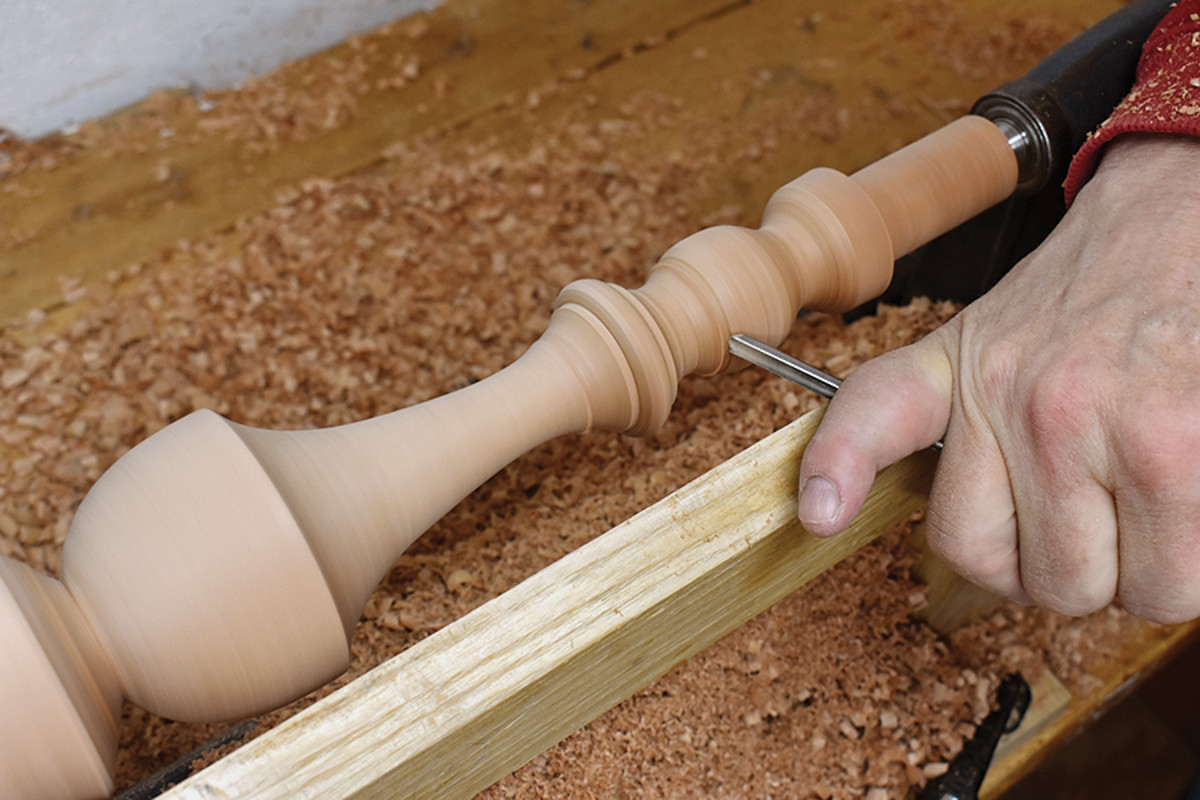
Legs & drops. Although to the naked eye the turnings on this table appear to be nearly identical, actual measurement would reveal considerable variation.
I then cut the various beads, coves, vases and fillets. I formed the beads with the tip of my 1⁄2” skew, the coves with my 1⁄4” gouge (its bevel snugged up against the work) and the fillets with an upside-down chisel. Before sanding each piece, I reduced the tenons to their 1⁄2“-diameter finished size.
The feet and drops were created in the same way: I established the greatest diameters with my roughing gouge, then articulated the details with a skew, gouge and chisel.
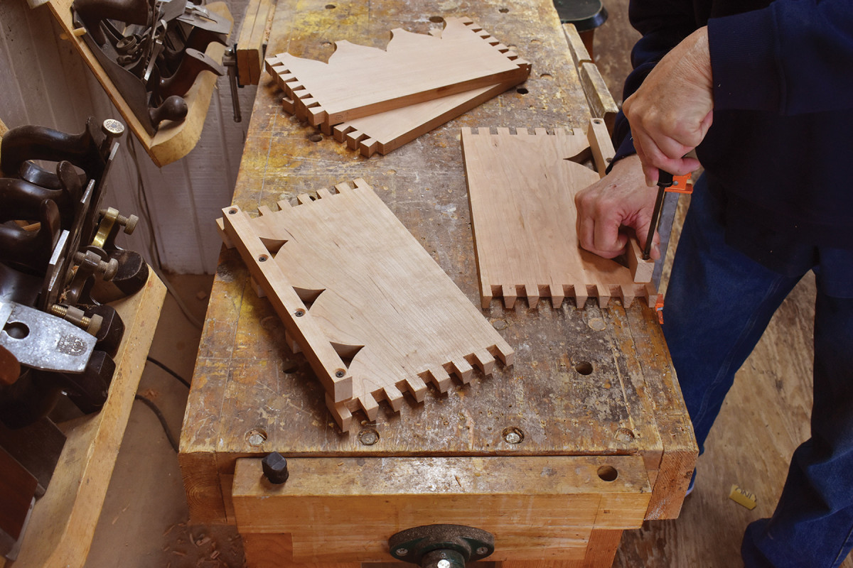
Dovetailed Aprons
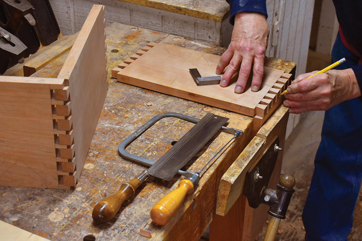
Dovetails. I mark my baselines 1⁄32″ deeper than the stock thickness (and cut tails-first).
As much as possible, I’ve removed machine tools from the fussy work of cutting joints. I’ve done this because I’ve grown to love those quiet times at the bench when I’m cutting joinery by hand. For this reason (and because I’m not smart enough to figure out how to use a router dovetail jig), I cut the dovetails on the apron by hand.
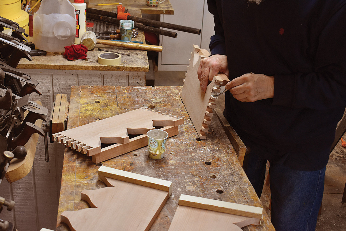
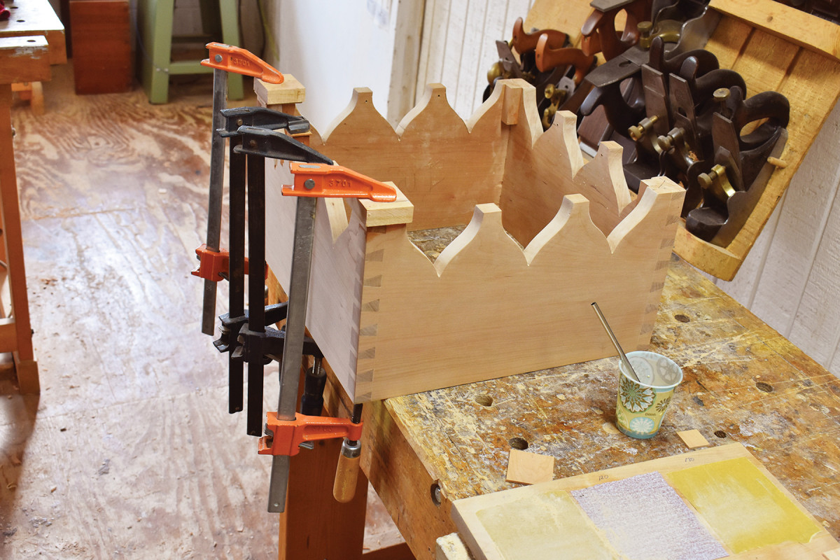
Arch support. Grain runout in the Gothic arches makes them susceptible to breaking under clamp pressure during glue-up. To reduce the risk, screw a caul to the inside faces of pin stock as shown here. (The screw holes won’t be visible on the finished table.)
Because of the fittings hand-cut dovetails require and the stress those fittings can impart to the components, it’s important to cut the joinery before sawing out the arch shapes at the bottom of each apron section.
On the case. Glue is both cheap and incredibly strong; apply it to all mating surfaces.
My dovetailing process is simple. I saw out the tails, which defines the sides of each one with a backsaw, remove the bulk of the waste with a coping saw and, finally, clean up the bottom of each pin space with a paring chisel powered by a mallet. I then clamp the pin stock in my vise, lay the dovetails on the edge of the pin stock and mark those pins with a pencil. After squaring vertical lines on the pin stock, I saw them out just as I did the tails.
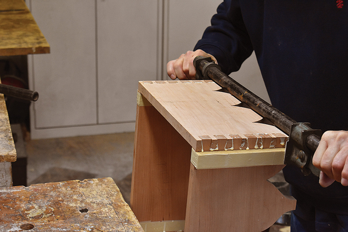
Gently tap the tails to start them in their positions, then seat them with slow pressure from a clamp over cauls.
After fitting the joints, cut the arches on the aprons, then fair and smooth the curves.
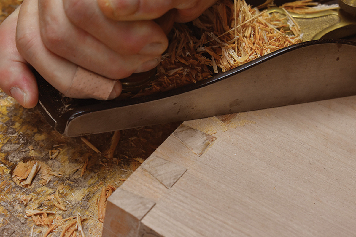
Flushed. Level the surplus length of the pins (if, like me, you choose that approach), and clean up the case.
Glue up the case and check its squareness by measuring diagonals (adjust as necessary). Position filler blocks flush with the leg locations, then set the case aside to dry overnight.
Serpentine Stretchers
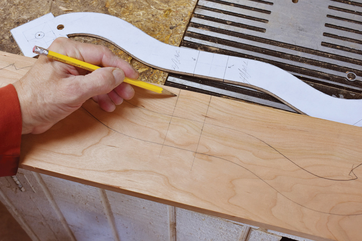
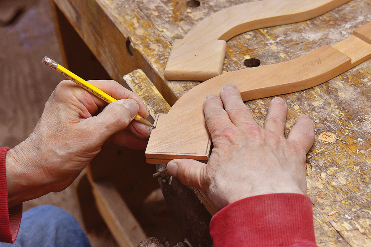
Stretcher layout. Square two lines 11⁄2″ apart across your stretcher stock. Place the pattern on the stock in a position that aligns the limits of the lap joint with the two squared lines on the stock, then trace the pattern.
Plane your stretcher material to a thickness of 1⁄2“, then square two lines across that material 11⁄2” apart. Place your stretcher pattern so the limits of its central square align with those squared lines in a position that allows the entire stretcher component to be drawn on that material.
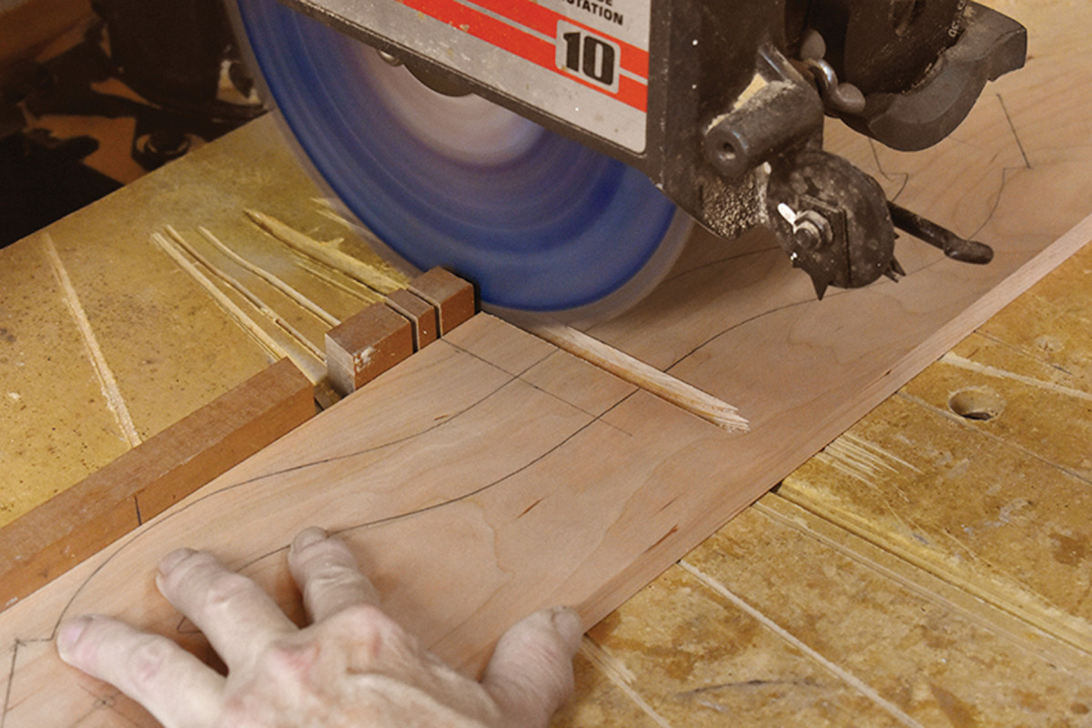
Lap joint. I use my radial arm saw to cut the waste from the lap joint to a depth of 1⁄4″ (half the thickness of the stretcher stock).
Before you cut out that shape, excavate a dado between the squared lines that is a depth half the thickness of your material, in this case 1⁄4“.
Saw out the shape of the first stretcher component, then use it and the stretcher pattern to establish in your mind on which side of the second stretcher component you’ll cut the matching dado for the lap joint.
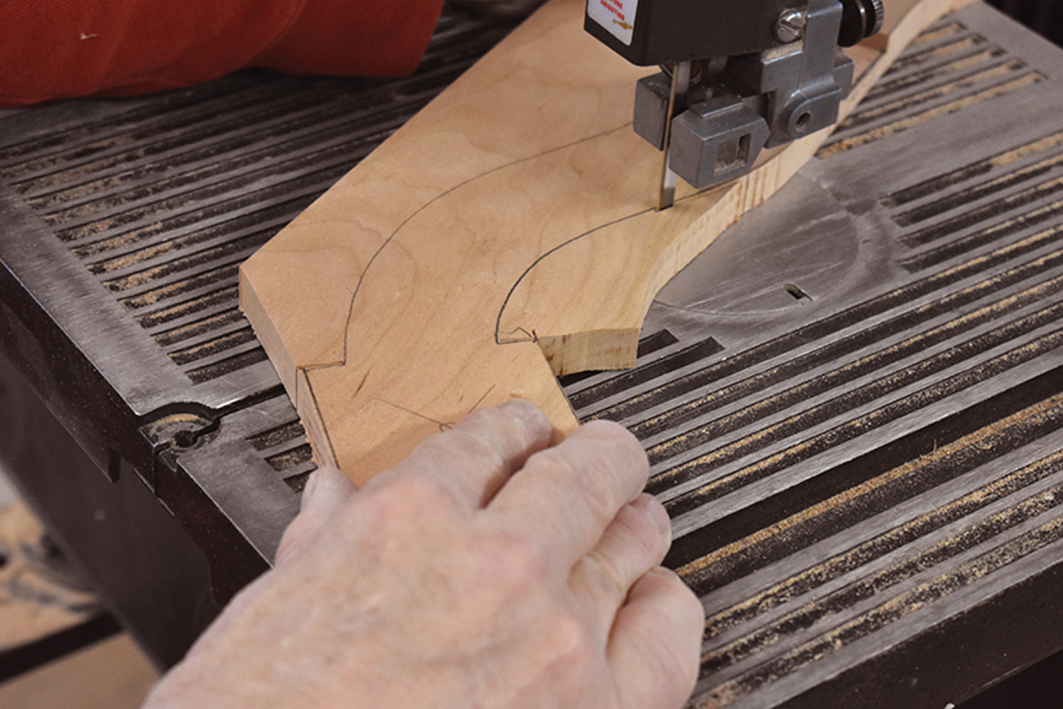
Cut the curves. I use a band saw to cut out the stretchers, then fair and smooth the curves by hand.
Remember that the right and left sides of the finished stretcher assembly must be mirror images – the placement of this second dado determines whether or not you achieve that bilateral symmetry. Cut the dado on the wrong side and you’ll end up with a strange-looking stretcher assembly – you know, like I did my first time out.
This next step is optional. I applied a gentle radius to the squared ends of the stretcher components simply because I liked the way it looked. If you choose this option, begin by establishing three lines on the edges at the end of each stretcher. You could create these lines by measuring, but I chose to eyeball their placement using my finger as a fence to locate the pencil point.
Square or eased? On some 17th-century pieces, the edges of X stretchers are simply squared. On others, the edges of the entire lengths of the stretcher components are radiused. The edges of my stretchers manifest a compromise; only the three sides of the square through which the legs pass are radiused. I like the look.
The first line should be drawn in the middle of the end’s thickness, leaving 1⁄4” of thickness above and below the lines. The two remaining lines are drawn on the top and bottom surfaces of the ends, approximately 1⁄8” from the edges.
Radii. I drew lines freehand to guide my block plane and rasp as I shaped the ends of the stretchers.
Using a block plane or rasp, create rounded surfaces connecting the lines on the top and bottom with that line in the middle of the component’s thickness.
 The final step in preparing the stretcher components is to bore 1⁄2” holes in the squared ends of both stretcher components, through which the feet are secured into the legs. The placement of these mortises is critical, so be sure that each is centered in the squared end. (The easiest way to find those centers is to draw a pair of diagonals across the squared ends. The center will be located where these diagonals intersect.)
Apply a bit of glue, assemble the lap joint, then reinforce the joint with a few countersunk 3⁄8” wood screws on the underside.
Add Some Cock Beading
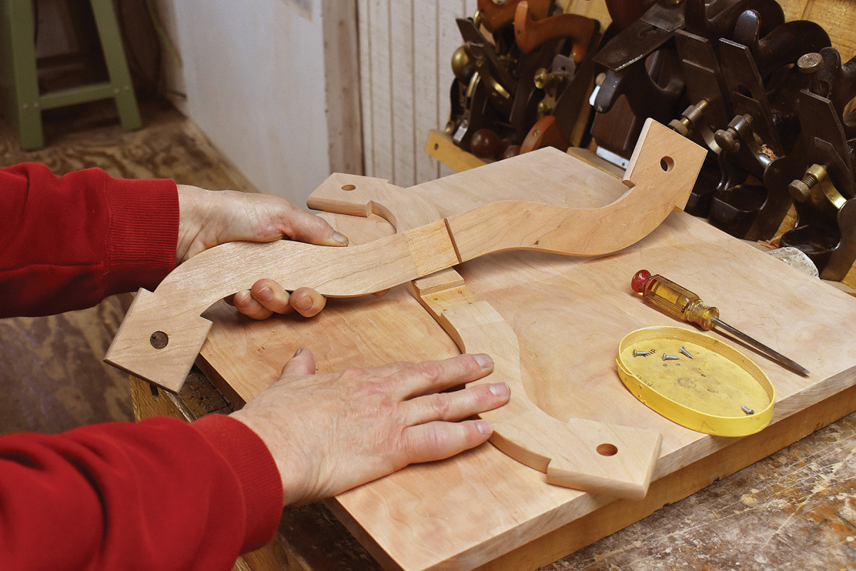
Ready to glue. With the holes bored and the lap fit, apply a little glue to the joint and assemble. Then reinforce the joint from the underside with countersunk 3⁄8″ screws.
There is a 3⁄32“-thick cock bead tile at the base of each of the Gothic arches. Those at the corners are 13⁄4” square; the intermediate tiles are 1″ square.
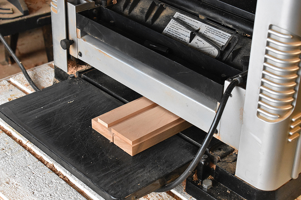
Safe machining. After you’ve ripped the cock bead stock to the finished width, attach the bead stock to thicker stock (a sled) with double-sided tape, then run that through your planer. (Or use a different method for thicknessing.)
Rip your stock to width, then plane it to thickness before cutting the tiles to final size.
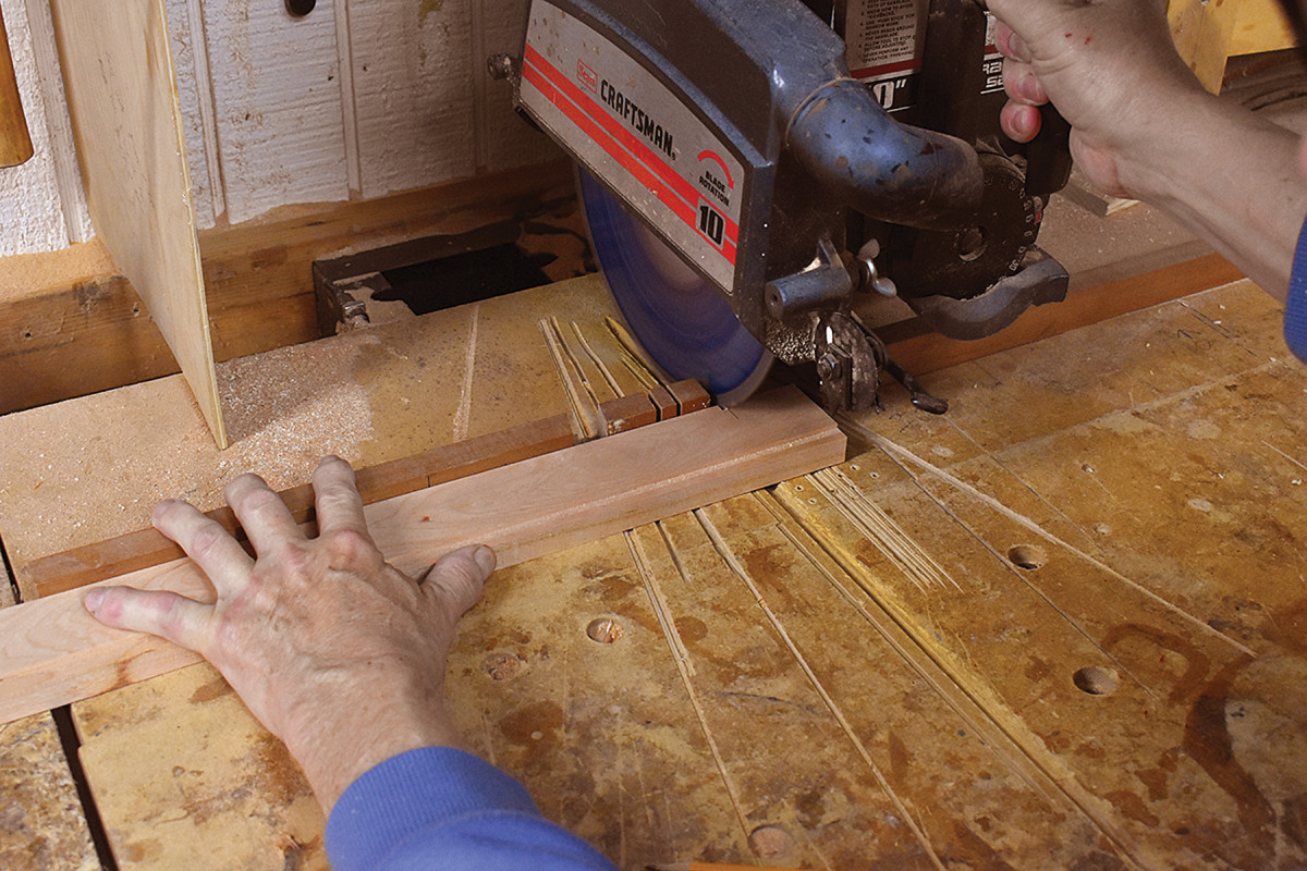
Leave it on the sled. It would be unsafe to use a radial arm saw (or miter saw) to cut the thin cock bead tiles to length – but leave the 3⁄32″ stock attached to the sacrificial planing sled and it’s OK.
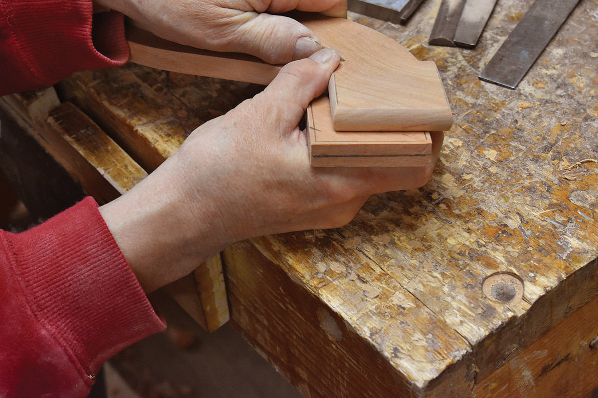
Ease all four edges of each tile to a gentle radius and finish-sand before gluing each tile in place.
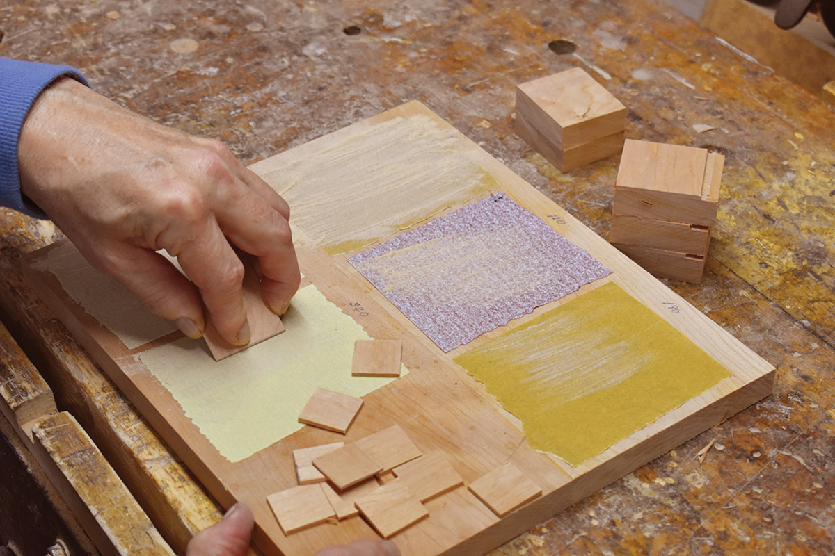
Grit work. I used spray adhesive to affix small pieces of sandpaper in grit progression to a piece of scrap, then eased the edges of each tile to a pleasing radius.
Then drill 1⁄2“-diameter holes for the leg tenons and 1⁄4“-diameter holes for the drop tenons using Forstner bits at the drill press. While the 1⁄2” bit is in your drill press, bore the leg mortises centered in the feet.
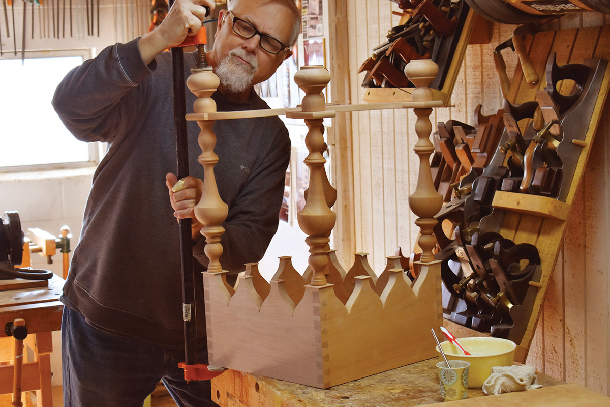
Clamping cauls. Add a drop of glue, then carefully position and clamp each cock bead tile centered on its leg or arch location. Because of the width of the corner tiles, it’s necessary to apply pressure indirectly through the use of a caul slightly larger than the tile.
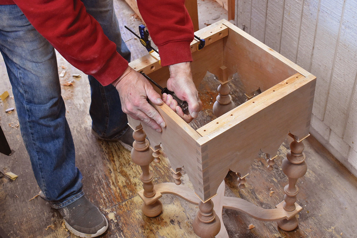
At this point, you’re ready to put things together. I recommend a dry assembly to ensure that everything is just the way you want it. When you’re satisfied with your work, apply glue to all the mortises and tenons and assemble the table’s undercarriage.
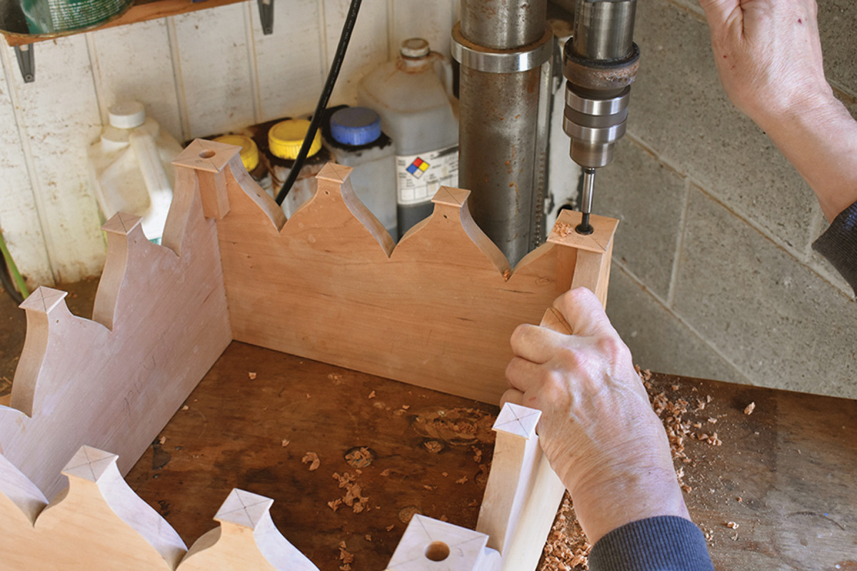
Round mortises. Use a 1⁄2″ Forstner bit to drill mortises for the tenons atop the legs, and a 1⁄4″ Forstner bit for the tenons atop the turned drops.
I glued up the 3⁄4“-thick x 181⁄2“-square top from three pieces, then moulded the edge using a combination of rabbets cut at the table saw and handplanes.
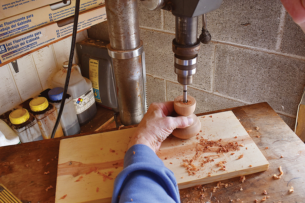
Pierced buns. The tenons on the bottom of each leg pass through the holes in the stretchers, and into 1⁄2″ mortises in the feet. These can be drilled while holding the foot in your hand. A Forstner bit imparts very little torque to the part being drilled. (I would never do this with a twist drill.)
The same look can be achieved solely with handplanes, or with a router or shaper; use the approach that fits your tools and skills.
Use the force. Although it isn’t necessary to leave the clamps on the legs while the glue dries (in fact, doing so can result in deformation of the table’s undercarriage), it’s better to pull parts together with a clamp than it is to bang it with a mallet because the force imparted by the mallet is explosive and therefore much more likely to result in cracked components.
I screwed 1″ x 1″ strips of hardwood through clearance holes to the underside of the top to position and attach it to the table base (see the pictures below), but you could use wooden buttons or commercial tabletop fasteners if you prefer.
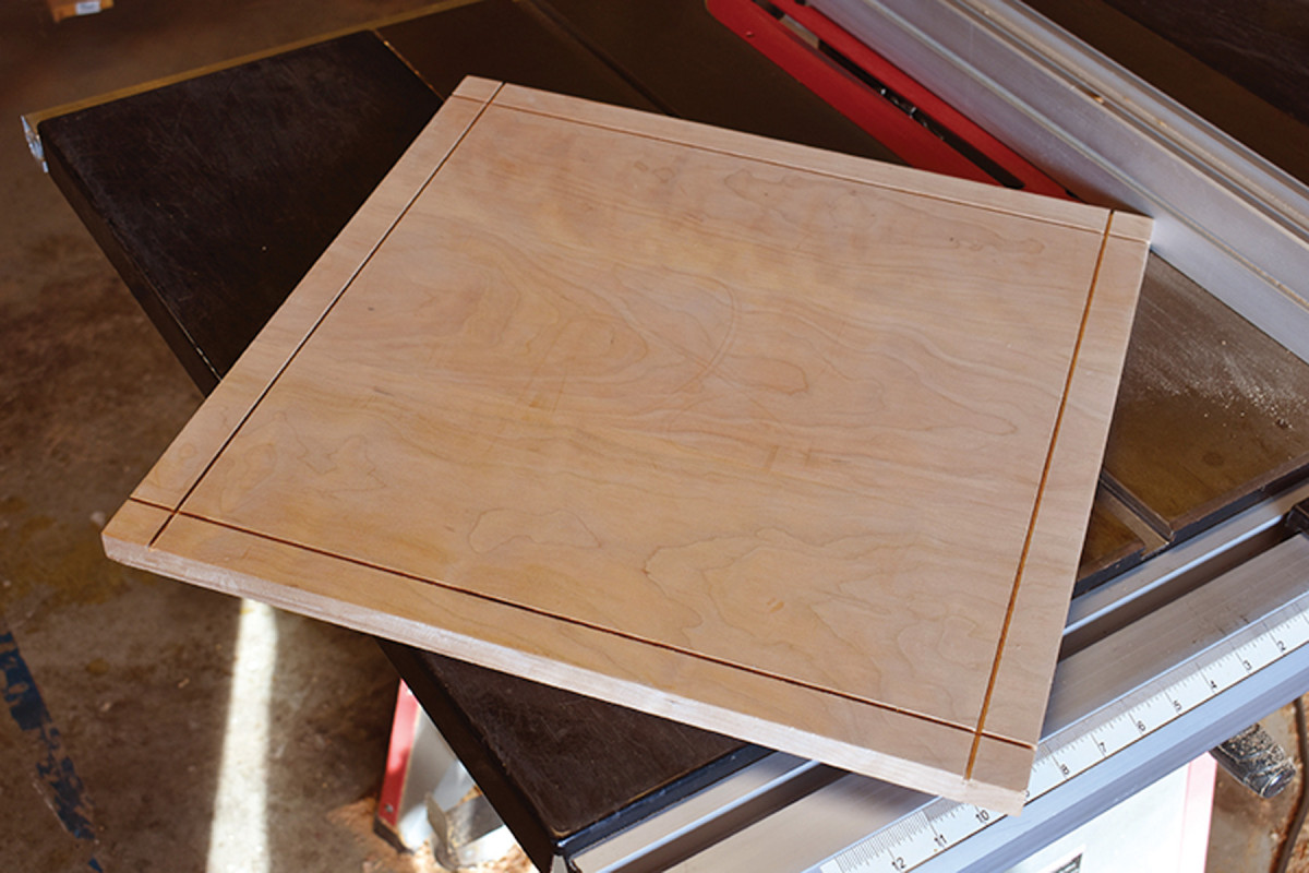
Sloped rabbets. My moulding method is to cut a rabbet by first making four 3⁄32″-deep cuts 1″ from the edges, then raise my table saw blade to 1″ and adjusting the angle slightly to cut sloped rabbets. Notice that I’m standing not at the back of the table as you ordinarily would, but at the side of the table opposite the fence.
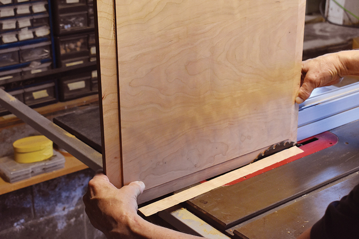
This position not only keeps me out of the zone in which kicked-back strips can be rocketed toward the user, it also gives me better control of the panel during its passage along the blade.
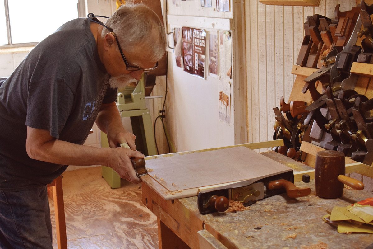
Fair the edges. After cleaning up the sawn edges with a wide shoulder plane, I use the same three-line method from the stretcher ends to cut a roundover on the edge of the top.
Finish as desired. (I used a matte polyurethane on the base and a gloss polyurethane on the top.)
Bedazzling Consistency
Get attached. I used 11⁄2″ #8 screws to attach two strips of 1″ x 1″ hardwood on opposing sides at the top of the aprons. After centering the tabletop on the base, I screwed the strips to the bottom of the top through clearance holes to secure it in place while allowing for seasonal movement.
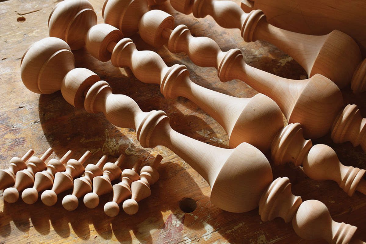
We live in an era of woodworking machinery capable of fabricating parts of incredible consistency – but that approach to woodworking is the antithesis of what takes place in my shop. Much of what I do is eyeballed rather than measured. This means there is variation in diameters between one leg and another, between the placement of coves and beads along the lengths of the leg, between the angles and widths of my dovetails, and in the widths of the two stretcher components.
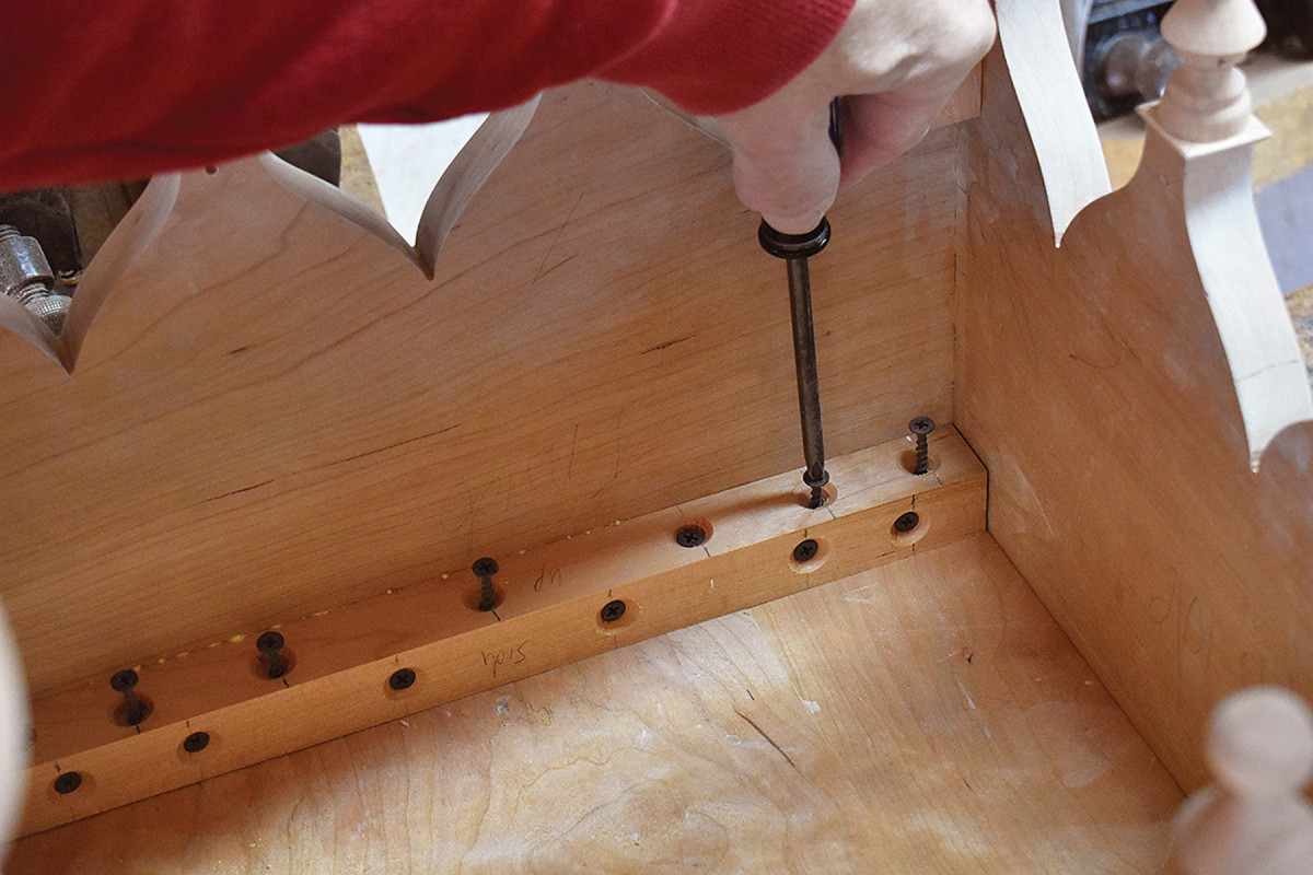
Note that the grain direction of the top is perpendicular to the length of the attachment strips.
I don’t deliberately create these inconsistencies; they are simply the result of the way I choose to work. When someone looks at a piece of my furniture, I want them to know that a human hand and a human eye were deeply involved in the fabrication.
Patterns: Download full-sized patterns of the legs, feet, drops and stretchers.
TableSideandLeg.pdf
ApronandDrop.pdf
LegandFoot.pdf
Stretchers.pdf
Here are some supplies and tools we find essential in our everyday work around the shop. We may receive a commission from sales referred by our links; however, we have carefully selected these products for their usefulness and quality.