In Projects

We may receive a commission when you use our affiliate links. However, this does not impact our recommendations.

Spring Joint Box

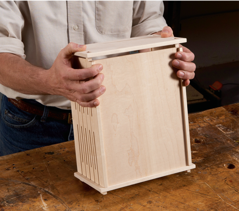
Self-locking design requires no glue.

By Randy Johnson

Squeeze and snap! That’s all it takes to assemble this CNC-routed box. Th e
joint’s flexibility comes from a series of slots that allow the hooked tenons to be
compressed, so they slide into the mortises. When released, the tenons spring
back into position, locking the parts together. While not as rigid as a glued joint,
the assembled spring joints are surprisingly stiff . And you can enjoy assembling
and disassembling the box as oft en as you like.The key to making this joint fit well—neither too tight nor too loose—depends
on several things. Th e primary factors are the spacing, length and number of
the slots as well as the tolerances between the tenons and mortises. Th e springjointed
front and back are also 1/8″ taller than the mortised ends. This small difference
in height keeps the hooked tenons slightly compressed aft er assembly,
which adds additional stiffness to the joint. Th e type of wood and the thickness
of the parts also affect the joint’s flexibility.Accommodating all these variables can be a bit of a challenge —I made eight
prototypes before I found a fit that I liked. But similar to mastering hand-cut
dovetails or mortise and tenon joints, the time spent working out a solution for
this box was a very satisfying learning experience.The slots become part of the box’s design and variations are almost unlimited.
However, I kept the shape and arrangement of the slots for this box simple in
order to show how the parts are made. Plans and tips for routing this box can be
found at AmericanWoodworker.com/CNC.
Click any image to view a larger version.
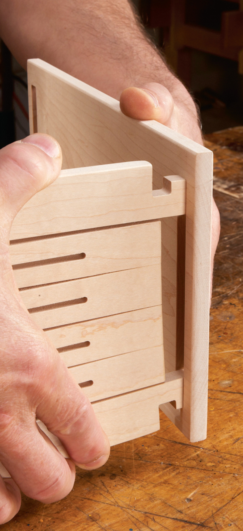
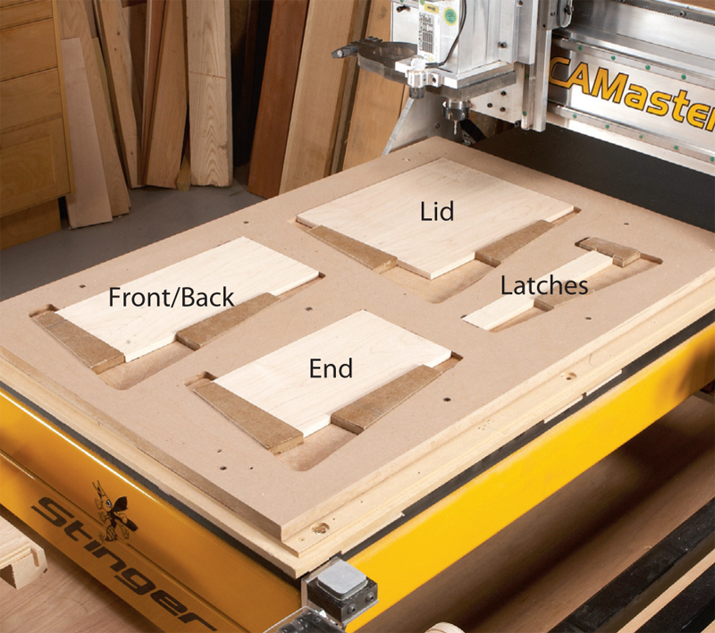
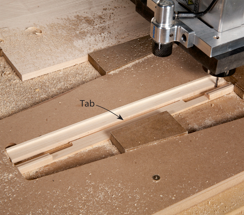
Wedge the parts in place

Holding parts secure is important for all CNC work. For
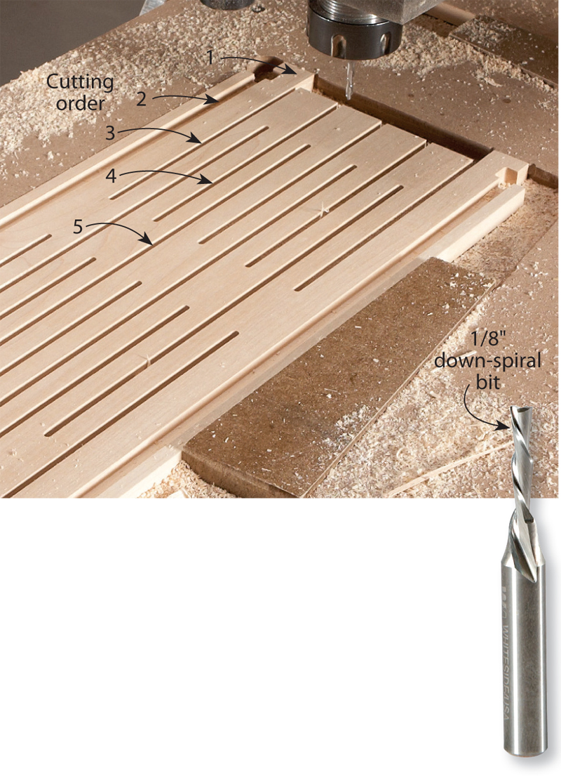
this project I used 3/8″ deep pockets—the same thickness
as the parts—cut into 3/4″ MDF. I then added 1/2″ thick
MDF wedges to secure the parts. The wedges are very
easy to install and remove with a couple mallet taps.

Rout the front and back parts

First cut around the tenons (1). Then cut the
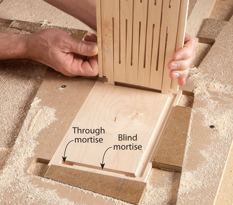
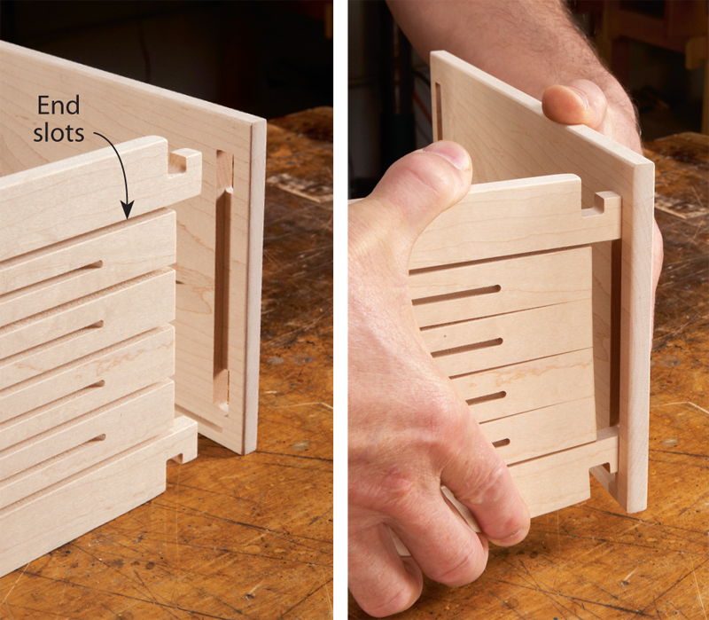
grooves (2), the two outer end slots (3), the three
inner end slots (4) and finally the center slots (4). This
cutting order is important because it keeps the router
bit from chattering as the part becomes increasingly
flexible. It’s also important to use a down-spiral bit,
which pushes the part down during routing.

Test-fit the parts

Rout the mortises and check the fit of the tenons. The parts
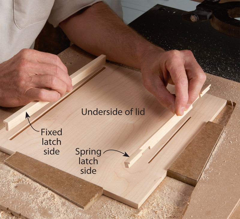
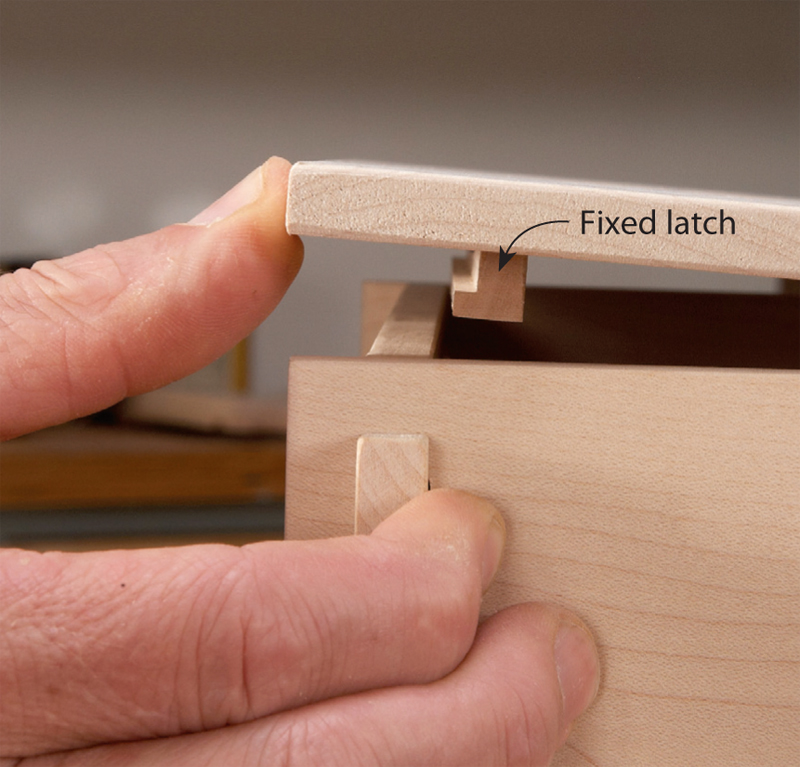
should fit together snugly, but without binding. I found cutting
the mortises .015″ larger than the tenons provided a good,
slightly tight fit. Once the faces of the parts were finish-sanded
and the corners were eased, the fit was perfect.

Rout the latch parts

The lid’s two latch parts are cut from one piece of wood but
connected with a thin tempoary tab between the parts. These
parts are somewhat delicate to machine, so the down-spiral
bit really proves its worth. An up-spiral bit can lift the parts and
chew them up—I speak from experience!

Test fit the latches

Rout grooves on the underside of the lid for the latch
parts and test their fit. The groove for the fixed latch runs
the full length of the latch. The groove for the spring latch
is shorter, since the ends of the spring latch must be free to
flex (as shown below, “Working the Spring Latch”). The latch parts are glued into
the slots after all the parts are sanded.

Assemble the first three parts

Two dimensions are key to making this joint work. First, the
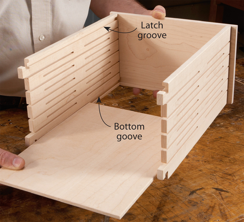
five 1/8″ wide end slots allow the tenons to be compressed up to
5/8″. Second, the through mortises are spaced so that the hooked
tenons only need to be compressed 1/2″ to pass through. This
1/8″ leeway eases the assembly. Anything less than 1/8″ makes
the parts difficult or impossible to assemble.

Insert the bottom panel

The 1/4″ thick bottom panel fits into grooves in the front and
back parts. These parts also have grooves near their top edges,
which serve as clips for the two latch parts. These grooves are
all the same size, so the front and back parts don’t have a top or
bottom. The ends have a single groove for the bottom panel.

Snap on the last part

Slip the remaining end over the hooked tenons, working the
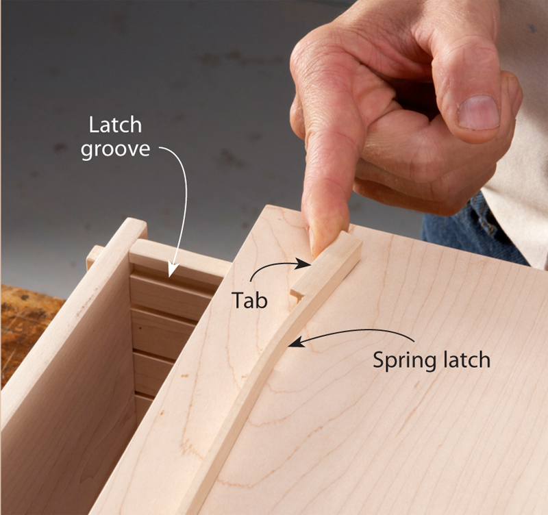
mortises down equally. Pressing one side down first will only rack
the end and cause it to bind. If the parts have been correctly cut,
this last end should snap into place with a satisfying pop. If not, a
little additional sanding should ease the fit.

Working the Spring Latch

Opening the box is a bit of a puzzler, because the springlatch
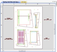
system is completely hidden when the lid is closed.
Here’s how the system works: Tabs at the ends of the spring
latch flex about 1/4″ (right, above). These tabs fit about 3/16″
into the latch groove in the back of the box. When the lid is
pressed from the front (right, below), the spring latch flexes
deeper into the groove at the back, allowing the fixed latch
to slip inside the box. Releasing the lid relaxes the spring
latch, which in turn engages the fixed latch in the groove in
the front of the box. The lid is now locked in place, because
both latches are clipped into the latch grooves. To open
the box, simply press on the front of the lid and lift.

DOWNLOAD VECTORS

Click here for DXF file for all project and jig vectors on layers and PartWorks and Vectric V-CarvePro file. This is a zipped folder.

This story originally appeared in American Woodworker December/January 2013, issue #163. DOWNLOAD STORY PDF

Product Recommendations

Here are some supplies and tools we find essential in our everyday work around the shop. We may receive a commission from sales referred by our links; however, we have carefully selected these products for their usefulness and quality.

Recommended Posts

Start typing and press Enter to search