We may receive a commission when you use our affiliate links. However, this does not impact our recommendations.
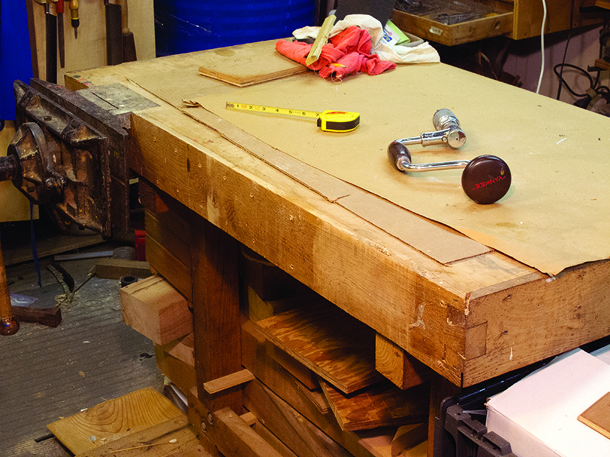
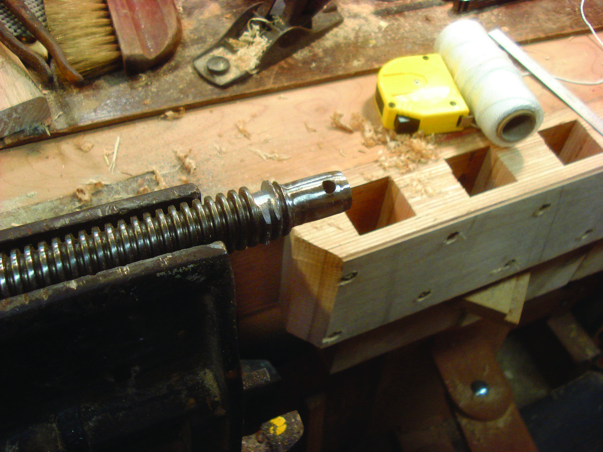
Perfect position. The front edge of my torsion-box benchtop is the perfect location for a tail vise with a movable dog.
Transform your workbench with custom-fit workholding – without any fuss.
For many woodworkers, especially those of the Galoot persuasion, a workbench with a tail vise of some sort is a fundamental necessity. These vises are integral to most European-style benches, and there are now extraordinary aftermarket options, some of which I own. But what are your choices if you don’t happen to possess one, or if one of the manufactured vises doesn’t fit your needs?
One of the great benefits of craft skills, for me, is the ability to change and form my immediate working environment to fit my preferences and expand my productive capacity. The recent addition of a shop-made tail vise to my old torsion-box workbench demonstrates this perfectly. You can easily adopt and adapt the principles and construction techniques I used to your own situation.
 The resulting accessory is sophisticated and elegant, and it transforms your bench. But it does not require extraordinary tools or equipment to make. If you have access to a good table saw and drill press, a few standard hand tools and have reasonable measuring and layout skills, you can knock this out in less than a day.
My workbench was the first major project I undertook after we moved almost three decades ago, with a limiting factor being the small space I had to occupy. The final result was a stout little bench with an incomparable Emmert K-1 vise from an earlier stint as a foundry patternmaker, and a 48″ twin-screw face vise. As I gravitated toward more handwork, I became increasingly dissatisfied with the absence of a tail vise with a movable bench dog to hold lumber flat on the benchtop. My solution was to create a homemade tail vise that’s easy to replicate.
In recent years, the proliferation of interest in workbenches and vises has led to an embarrassment of riches along these veins, including several excellent “off the shelf” alternatives. Many, however, require either extreme modifications to an existing workbench, or the construction of a new bench altogether.
My bench has a torsion-box top rather than a solid slab, so most of the available products were not viable. Instead, using mostly parts from industrial supply vendors and some 1⁄2” Baltic birch plywood, I was able to retrofit my bench with an excellent tail vise. It nestled exactly into the space I had to perfectly serve my needs.
Quad-layer spacers. Blocks of four layers of Baltic birch plywood are glued with hot hide glue and standard shop clamps. All of the wood components in this project are Baltic birch plywood.
This “add-on” feature employs the long-standing concept basic to all tail vises – a fixed dog embedded into the top of the bench paired with a in-line moving dog – to provide the holding function for my workpiece. The end result is a bolt-on enhancement that can immediately change both your work habits and capacity.
I had two design considerations. The first was the unalterable dimensions involved. My workbench top is 5″ thick, and the length of the space available for a retrofit along the front edge of the bench was 32″. Second was my increasing attraction to wheel-handled vises. I decided to give my vise an 8″-diameter recycled wheel handle, which required me to design the vise so the wheel did not extend above the benchtop.
Construction began by cutting the 8″ x 32″ front and rear plates, and gluing up some quadruple-laminated spacer blocks made from Baltic birch plywood. The blocks are the same width as the plates.
The size of these pieces reflected both the bench thickness and the depth necessary for the hand wheel to fit on the screw that drove the moving carriage back and forth. One of the blocks is used at the business end of the unit as the platform for laying out and assembling the guts of the vise. A second block fits near the mid-point of the unit, as I later describe.
Shop-made Tail Vise Cut List
No.ItemDimensions (inches)Material
t w l
❏ 2 Front/rear plates 1⁄2 x 8 x 32 Baltic birch plywood
❏ 1 Wheel end block 2 x 2 x 8 Baltic birch plywood
❏ 1 Carriage block 2 x 6 x 8 Baltic birch plywood
❏ 4 Spacer blocks 2 x 3 x 8Baltic birch plywood
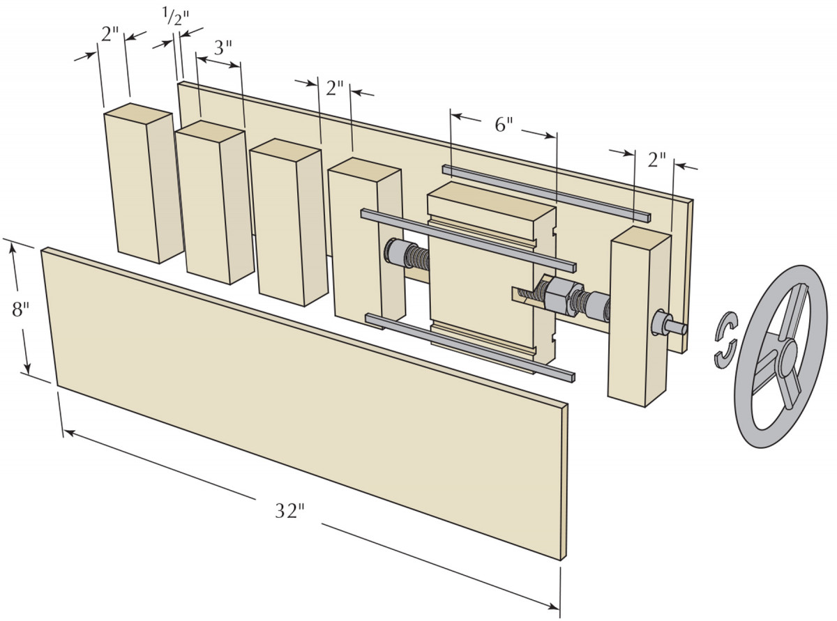
Exploded View
Design & Build the Carriage
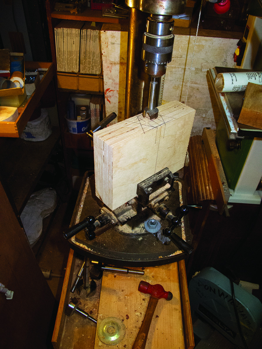
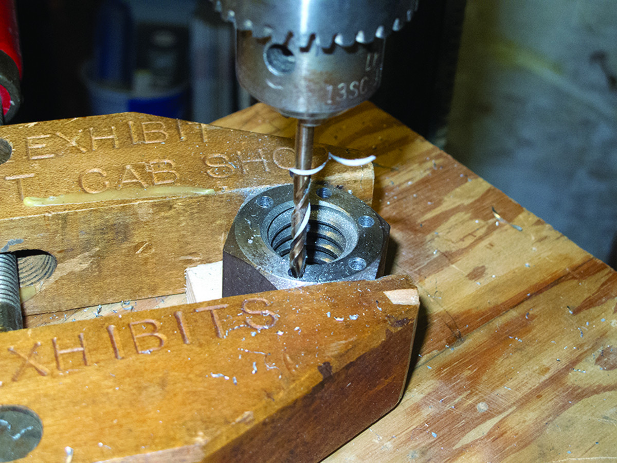
Exacting setup. This cross-feed table on my drill press facilitates drilling the concentric holes for the screw and bronze sleeve bushings. Start with the larger hole first, then the smaller hole inside.
The next step is to decide the length of the movable-dog carriage, and how much you want it to move. These are essentially arbitrary choices. I chose a 6″-long carriage with 6″ of travel. On the other hand, these are not entirely whimsical decisions because they determine the spacing of the fixed dog holes. In other words, if your carriage travels 4″, you need to have fixed dog holes every 4″ down the length of the vise. After this was established, I cut the 2″-thick blocks to serve as my dog spacers, and my carriage.
The dimensions of the end blocks were determined after the rest of the structure was laid out and assembled. Prior to constructing the moving carriage block, glue the spacer blocks to either the front or rear plate.
In this tail-vise configuration, the carriage moves along a threaded rod that penetrates horizontally through it. The rod also runs through a nut attached to the carriage. I chose left-handed, or reverse thread, 1″ Acme-thread stock because it makes the carriage work similar to a typical end vise.
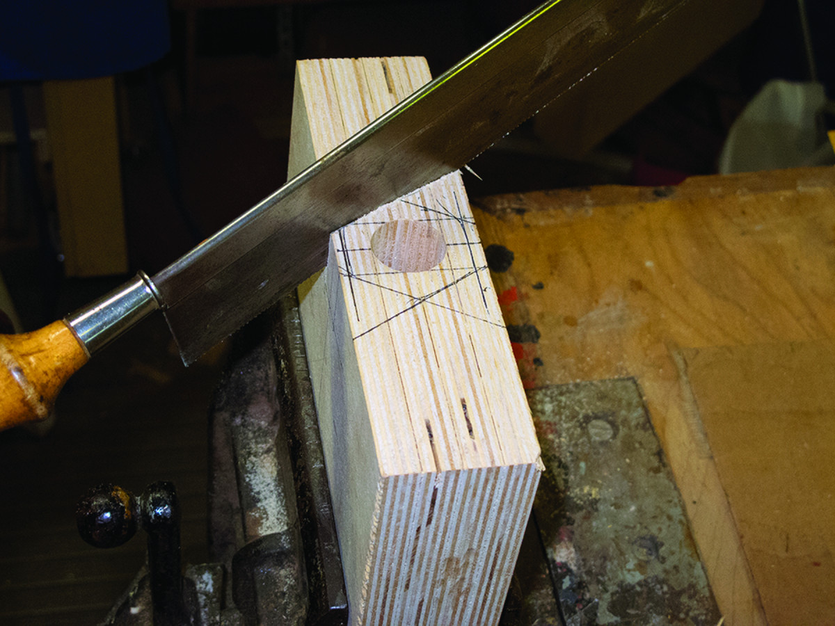
Quickly defined. A simple backsaw makes it quite easy to cut the outlines for the cavity into which the nut will go.
To install the setup, I first established the top-to-bottom centerline of the wheel handle, and the front-to-back centerline of the carriage block on both ends. I then drilled a hole in one end to accommodate a bronze sleeve bearing for the trailing end of the threaded rod. On the other end I drilled a 1″ hole to fit the threaded rod itself.
Because my drill press does not have enough travel to do the job in one step, I drilled the hole as deep as the press would allow then retracted the bit. I raised the drill press table to where the drill bit fit inside the workpiece hole, clamped everything in place and finished the hole through to the opposite side.
I don’t own – and hope to never have to purchase – any left-hand thread taps and dies. I needed to install the left-hand thread, 1″ Acme nut into the carriage block to serve as the engagement for the threaded rod. I threaded the nut onto the rod, inserted it into the carriage block then marked the outline of the nut on the block.
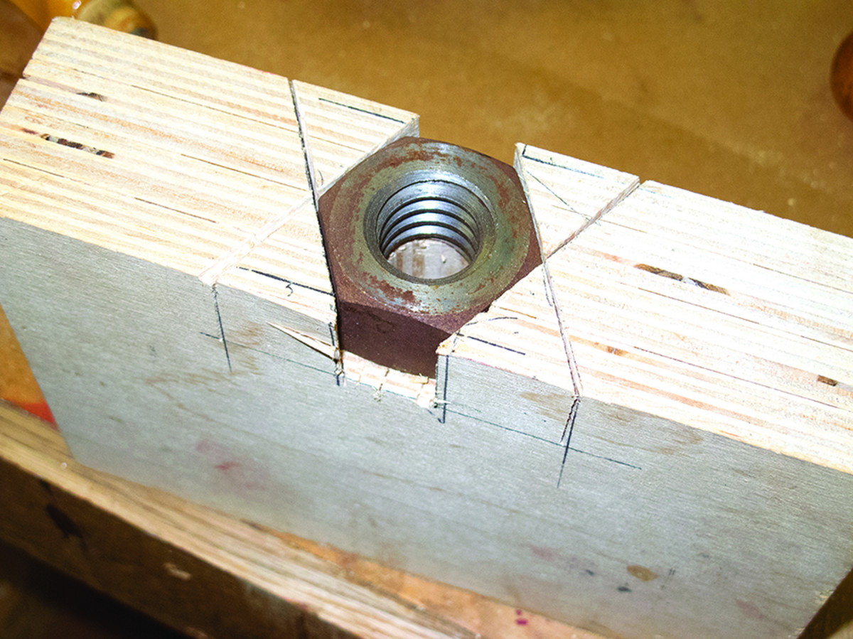
Sitting just right. Fitting the nut is perhaps the fussiest part of the whole project. Make sure it aligns with the thread-screw hole and is flush with the surface.
Using a backsaw I sawed the lines of this hexagonal outline, then excavated the cavity with a hammer and chisels until the nut seated firmly and squarely in the void. I then attached the nut to the carriage with screws through countersunk holes drilled through the nut.
The Carriage Guides
One at each turn. I drilled and countersunk six holes around the perimeter of the nut, then screwed it into the carriage block’s hexagonal cavity.
The last phase for the carriage was to create guides or “ways” which keep the carriage riding square while in use. (Almost any hard, smooth material will suffice for the ways, but I chose steel stock from my scrap drawer.)
With a dado stack, I cut 3⁄8” x 1⁄4” grooves about 1″ from the top and bottom edges of the carriage, on both the front and back plates. I drilled three small countersink holes into each of the four rectangular rods to allow easy attachment to the inner faces of the front and rear plates.
Locating the ways is easy. Place the carriage against the inside of the rear plate in the correct position, making sure to get the block aligned exactly with the top of the plate. Insert two of the ways into the carriage block with the countersunk side up then attach the ways to the plate with appropriate-sized flathead screws. Repeat on the other plate.
Your choice for dogs in the moving carriage is entirely up to you. Removable doweled blocks work fine as a dog on the top of the carriage, as do rising bench stops or a simple threaded set screw.
At some point I’ll try to talk myself into installing fancy dovetailed dogs (like those on H. O. Studley’s bench) into each end of the carriage, but for now any of the former options work fine, as will a large screw countersunk to be level with the top surface of the carriage.
Final Assembly
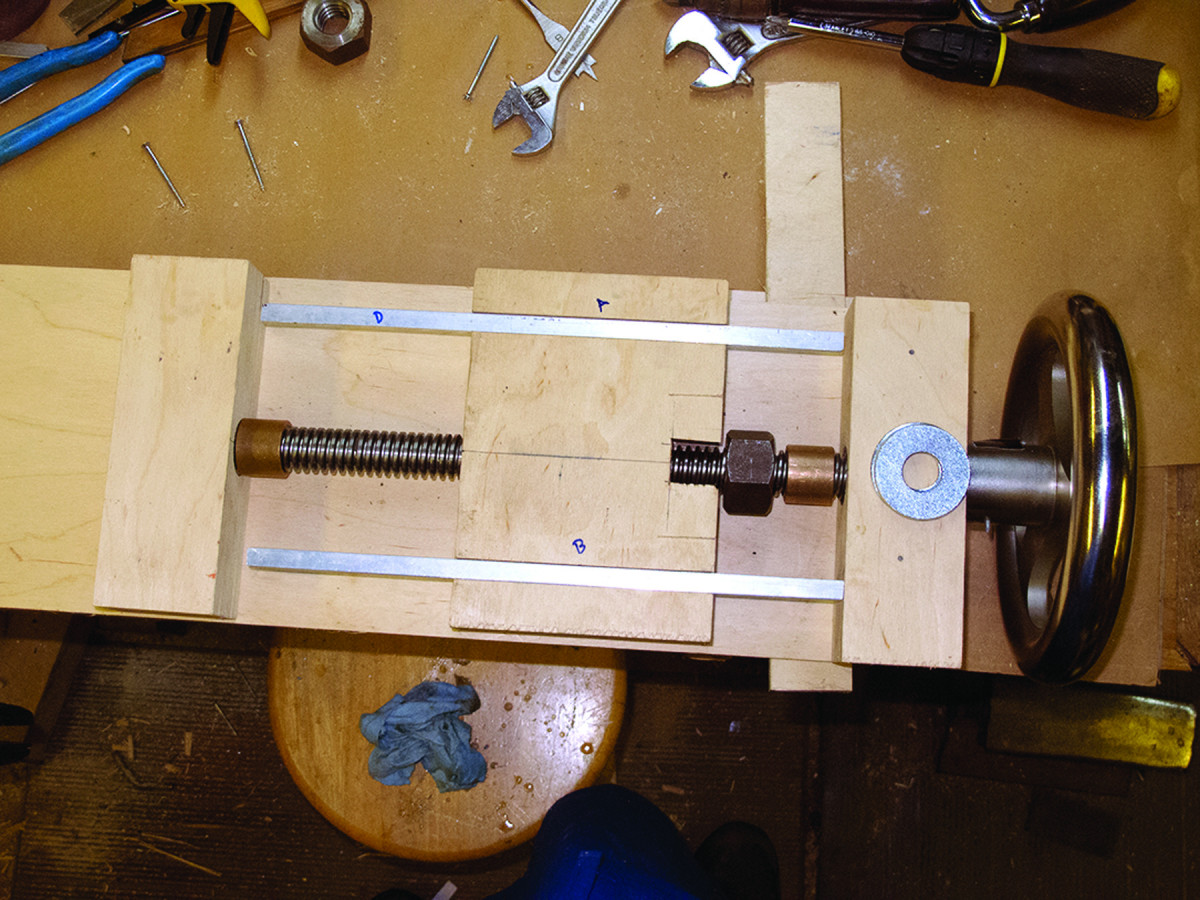
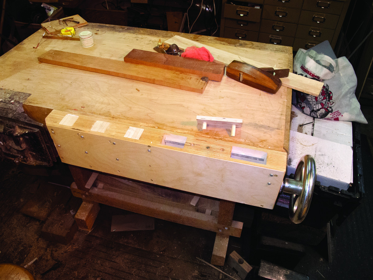
Just like this. Here, you can see the complete moving carriage setup prior to final assembly.
Once the carriage was completed, I drilled a hole in the first fixed spacer block to accommodate another bronze sleeve bearing, and glued the block in place – this bearing assures a wobble-free performance for the carriage until long after my ashes are spread on the mountain behind my barn. The remaining spacer blocks were glued in place based on the dimensions of the dogs themselves. I chose square cross-section dogs that measure 2″x 2″, and are 8″ long.
On the back of the fixed block at the wheel end of the setup, I drilled a precise hole to hold a final sleeve bearing.
On the handled end of the threaded screw, I had to grind, file or machine the rod to accommodate the wheel, then dry-fit the assembly, including the movable carriage, its two retaining blocks and the hand wheel.
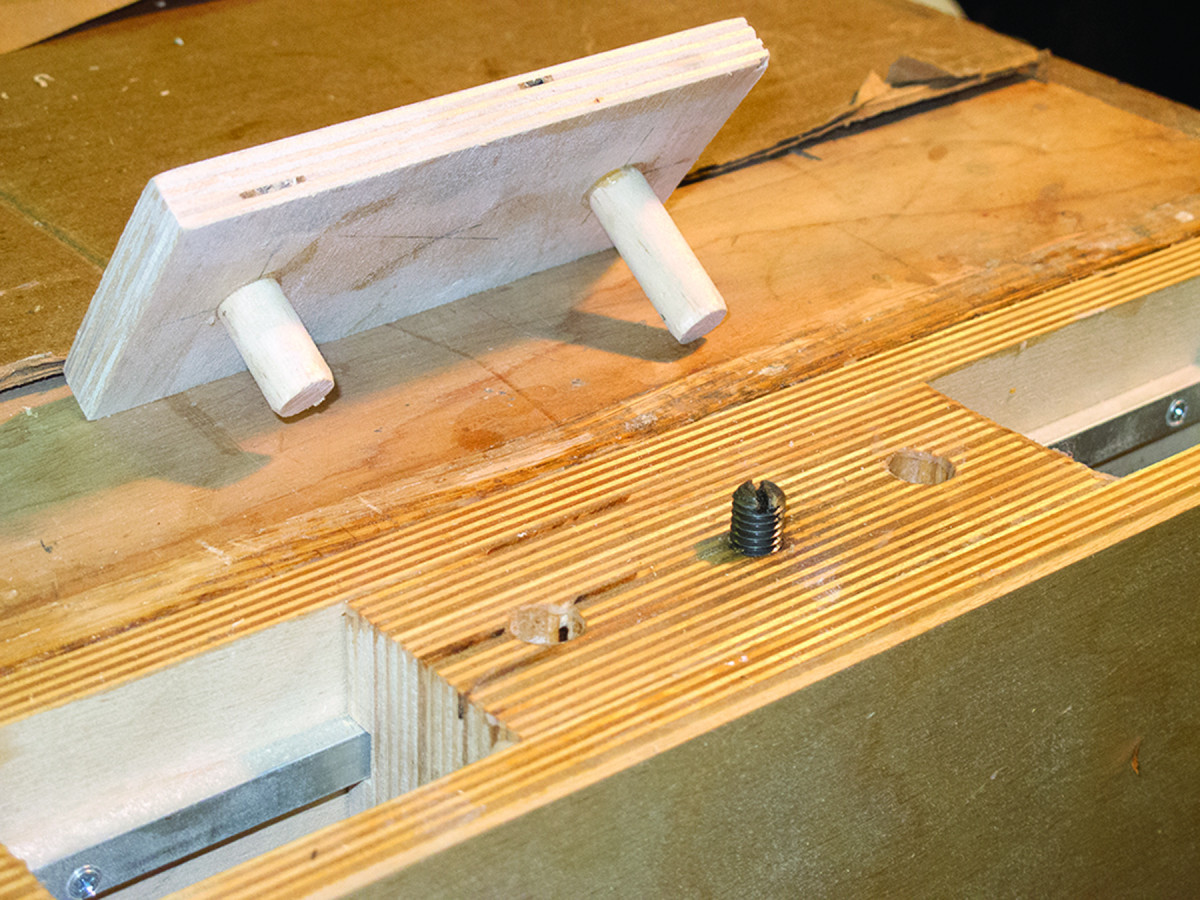
Two methods. I elected to use removable dowel blocks and a simple threaded set screw for my moving carriage.
With the pieces all in position, I noted the outer surface of the fixed-end block on the rod. This locates where to cut a groove around the circumference of the thread stock for a garter.
The fittings to retain the drive screw are standard 3⁄4” inside-diameter washers – to make the connection robust, I used two washers stacked together.
The outside measurement for the drive screw is 1″, so I figured an 1⁄8“-deep groove the width of two washers would be easy enough to cut with a file (or with my machine lathe if it came to that).
Get the job done. While a lathe makes this step effortless, careful use of a grinding wheel and file can accomplish the same end, although not quite as beautifully.
I marked and drilled the screw holes on my drill press, although a handheld drill would certainly suffice.
After drilling the holes with both washers aligned, I countersunk the holes on the outer washer. Using a hacksaw, I cut each washer in two, with the cutline turned 90° from the outer washer to the inner washer. This ensured unbreakable strength for the composite garter.
The only thing left is to assemble the entire unit, attach it to your bench, and get to work. I found my vise to be a bit stiff at first as all the pieces were seating in, but once that happened, it worked smoothly and easily.
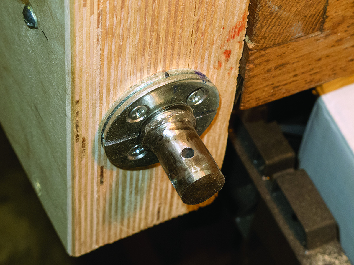
Ingenuity at work. The split garter is actually a pair of split washers in disguise. The end of the rod is modified to accept the hand wheel.
By following and adapting the ideas here, I believe you too can add a moving-dog tail vise to the front edge of your workbench. The advantages are to make your bench exactly the way you want, and to avoid making a new bench or radically modify an existing bench. Plus, it provides the undeniable pleasure of making something exceedingly useful. It just might change forever the character and capability of your bench and the way you approach our craft.
Here are some supplies and tools we find essential in our everyday work around the shop. We may receive a commission from sales referred by our links; however, we have carefully selected these products for their usefulness and quality.